Application and Operation
6.5 Command Generator
Product User Manual
Operating Instructions, Version AE 12/2009, A5E01454341C
119
6.5 Command Generator
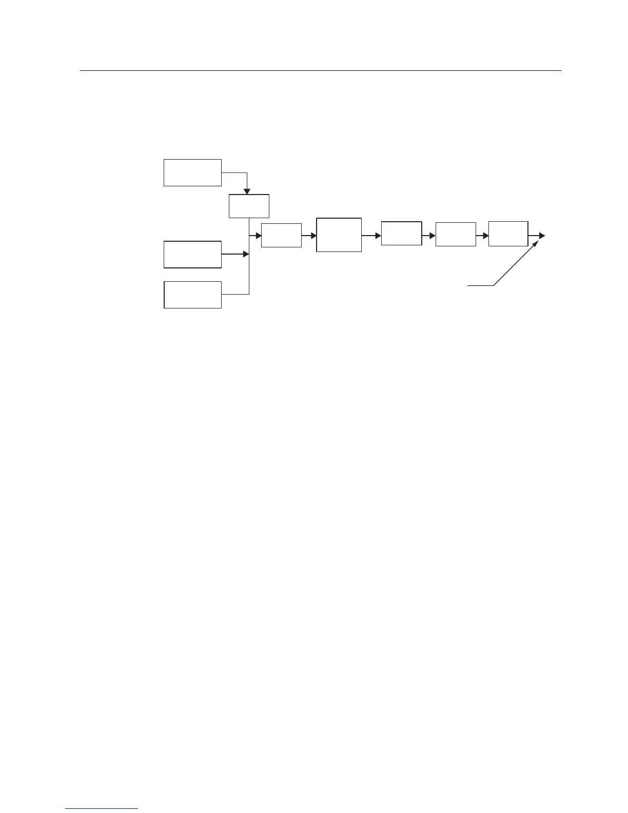
This section defines the Command generator functional blocks shown in Figure " Command
Generator"
$QDORJ,QSXW
6RXUFHV
5DWLR
&RQWURO
3,'&RQWUROOHU
6HWSRLQW6RXUFHV
6SHHG
3URILOH
&ULWLFDO6SHHG
$YRLGDQFH
3RODULW\
&RQWURO
6SHHG
5DPS
6SHHG
/LPLWV
5HIHUHQFH
Figure 6-5 Command Generator
6.5.1 Raw Speed Reference
The NXG Control includes provisions for output speed demand entry as required for a
specific application. The active reference source is configured per specific system
requirements and can be dynamically changed. This is implemented via the drive’s "System
Program" as defined in Section "System Program (SOP)". An overview of each of the major
functional blocks is defined next, and a detailed description is provided in the
NXG Control
Manual, 19001588
.
Analog Input Sources
The NXG control provides a means to provide multiple analog input sources that can be
selected as demand inputs to the system. The control scales these analog values into
internal units, and monitors the levels for possible loss of signal conditions. The control
includes provisions for predetermination of VFD action upon loss of signal conditions,
including maintain speed, transition to preset speed, or trip VFD.
Ratio Control
The Ratio control is simply a fractional scaling unit available for the analog reference signals.
This feature allows multiple drives to share the same reference signal with rescaled output
signal levels.
PID Controller
The PID loop is programmable from User Interface. The PID Command set point can be
either an external Analog Input or an internal set point. The PID Feedback is always from an
Analog Input. The Proportional, Integral, and Derivative gains, as well PID output limits, are
programmable.
 Loading...