Product Description
5.3 Cabinet Details
Product User Manual
Operating Instructions, Version AE 12/2009, A5E01454341C
87
Coordinated Input Protection Scheme
Input currents and voltages to the drive input transformer are measured and processed
continuously by the control system. Information such as efficiency, power factor, and
harmonics are available to the user. The input monitoring also protects against transformer
secondary side faults that cannot be seen by typical primary protection relaying.
Thus it is very important that the drive input medium switchgear, if not supplied as standard,
is interlocked to the control system so that input medium voltage can be interrupted upon the
rare event of such a fault.
A dry contact output is supplied standard with each drive to trip the drive input medium
voltage circuit breaker or contactor. This contact changes state whenever the drive input
power and power factor are outside hardcoded normal operating conditions.
DANGER
This contact must be integrated with input switchgear to deactivate the drive input medium
voltage upon the rare event of a secondary circuit fault.
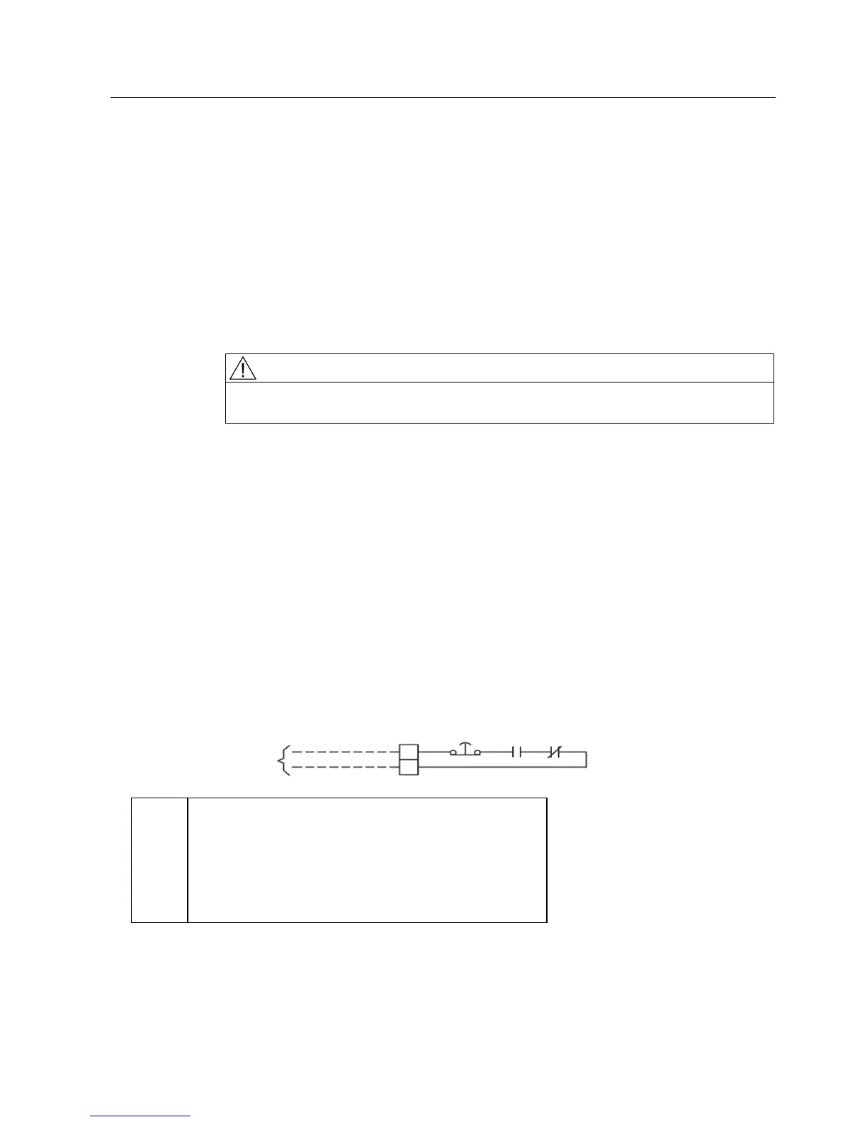
This scheme is active on all GenIV drives. Therefore, a medium voltage input circuit breaking
device is required. As shown in Figure "Input Protection Interface for Trip Contact" below, the
latch fault relay, LFR, and its reset switch, SW2, make a portion of the coordinated input
protection scheme. The drive control continuously meters the input power, and if the drive
exhibits excessive losses or reactive power, then a dedicated NXG II I/O digital output (IDO-
15) is closed as a one-shot pulse latches the LFR coil. This causes the N.C. LFR contact to
OPEN, and the NXG II I/O digital output IDO-14 also opens. As shown in the following figure,
if the contacts looking into the drive are closed, the user is permitted to close the incoming
breaker, hence the signal name "MV IP Breaker Enable". However, if the contacts are open,
then the input breaker must also be immediately opened. In addition to the Input Protection
scheme controlled by the NXG II Controller, GenIV also series connects one deck of the E-
Stop (PB4) in series with the Coordinated Input Protection Scheme. Therefore, if the E-Stop
located at the drive is operated, the contacts at TB2 will also open (this is only a portion of
the protection scheme that is subject to change, based upon user preference). To reset the
protection scheme, the LFR must be reset using SW2 (located in the Control Tub), which
immediately recloses the LFR N.C. contacts, and then a Drive Fault Reset must be initiated
(NXG Control will not re-close IDO-14 if the FAULT conditions still exist).
127( '$1*(57+,6&217$&70867%(,17(*5$7(':,7+,1387
6:,7&+*($572'($&7,9$7(7+('5,9(,13870(',8092/7$*(
83217+(5$5((9(172)$6(&21'$5<&,5&8,7)$8/7
&217$&76&/26(' 3(50,66,9(72&/26(%5($.(5
&217$&7623(1 75,3%5($.(5
09,3%5($.(5(1$%/(
6((127(
5$7,1*6
3%(6723
9$&$PS&RQW
$PSPDNH$PSEUHDN
',*,7$/2873876
9$&$$&
/)51&&RQWDFWV
9'&DQG9$&$
9'&$
9$&$
7%
3%
,'2
/)5
Figure 5-22 Input Protection Interface for Trip Contacts
 Loading...