Product Description
5.3 Cabinet Details
Product User Manual
Operating Instructions, Version AE 12/2009, A5E01454341C
91
Component Label Part Description
F33, F34, F35 Blower CBLW2 Fuses
1
(Optional)
CB10 Blower TBLW1 Circuit Breaker
2
CB11 Blower TBLW2 Circuit Breaker
2
(Optional)
CB12 Blower CBLW1 Circuit Breaker
2
CB13 Blower CBLW2 Circuit Breaker
2
(Optional)
STR21, AUX21, SUPP21 Motor Starter for Blower TBLW1, auxiliary contact, and AC
coil suppressor
STR22, AUX22, SUPP22 Motor Starter for Blower CBLW1, auxiliary contact, and AC
coil suppressor (Optional)
STR23, AUX23, SUPP23 Motor Starter for Blower TBLW2, auxiliary contact, and AC
coil suppressor (Optional)
STR24, AUX24, SUPP24 Motor Starter for Blower CBLW2, auxiliary contact, and AC
coil suppressor (Optional)
STR25, AUX25, SUPP25 Motor Starter for Blower TBLW3, auxiliary contact, and AC
coil suppressor (Optional)
STR26, AUX26, SUPP26 Motor Starter for Blower CBLW3, auxiliary contact, and AC
coil suppressor (Optional)
X6 2.5% Line Reactor for EC Blower TBLW1
X7 2.5% Line Reactor for EC Blower CBLW1
X8 2.5% Line Reactor for EC Blower TBLW2 (Optional)
X9 2.5% Line Reactor for EC Blower CBLW2 (Optional)
FLTR1 EMC Filter for Auxiliary Control Voltage (Optional)
PL2, PL3, PL4, PL5 Blower Control Disconnect Harnesses
1
These fuses are omitted when the circuit breaker option is selected
2
Blower circuit breakers are an option
The auxiliary voltage control transformer, X5, is protected by three fuses, which are located
in this section. F21 and F22 are located on the primary of the auxiliary control voltage
transformer, and F4 is located on the secondary of the transformer. These fuses are CC time
delay 600 V rated.
The EMC filter is typically used on agency projects requiring CE certification. FLTR1 is a
two-stage zero sequence filter rated at 7A, and when used, is applied between the
disconnect switch (DS1 in the Control Section) and the EC Blowers’ motor starter.
*1'
)
)
)
)
)
)
)
)/75
; ;
*1'
675
$8;6833
675
$8;6833
)
)
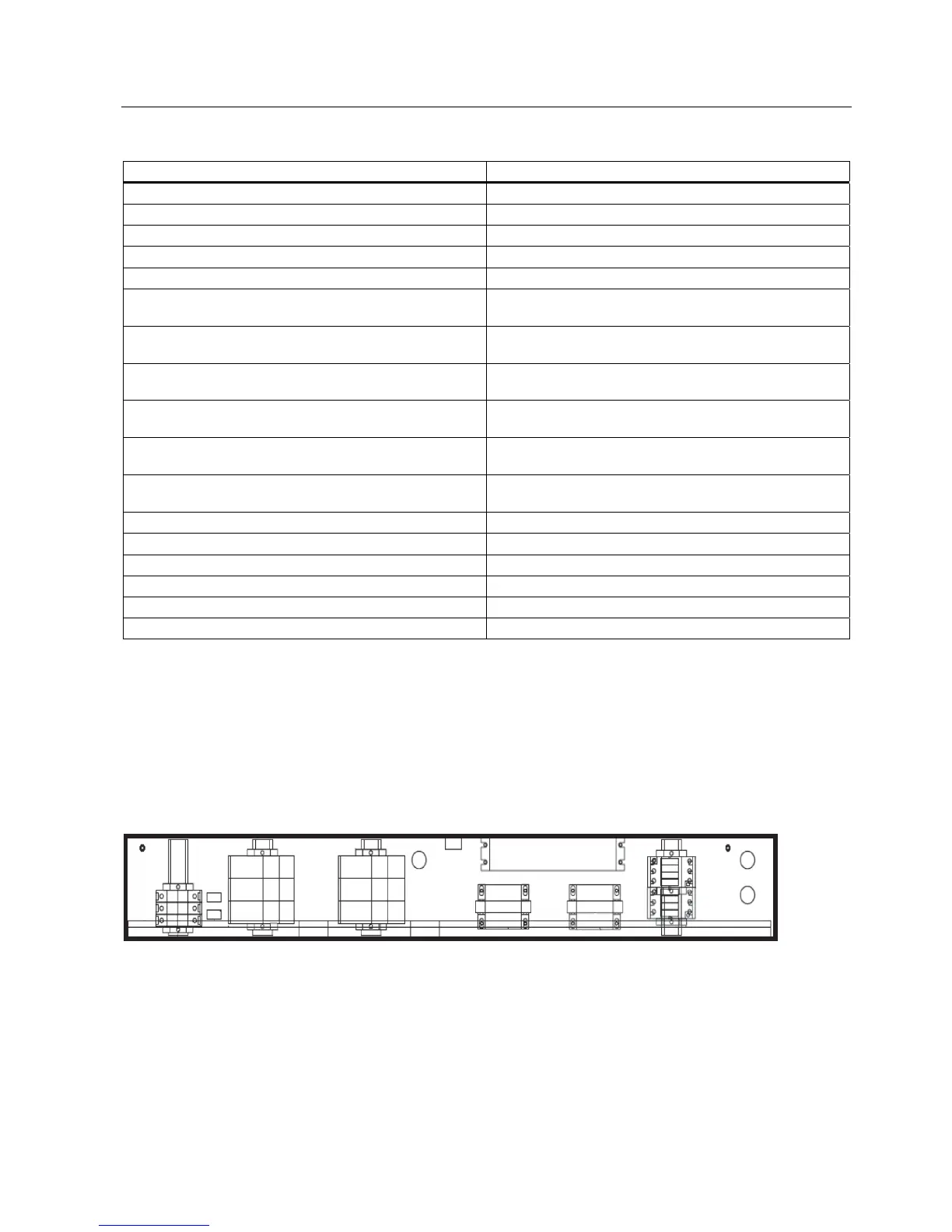
Figure 5-26 Control Wire Way Section (with all options)
Cooling System Control
The cooling system consists of several parts including either an EC or AC blower described
in the next section. In addition to those components, each blower has three 600V Class J
time delay fuses or a 600 V three phase 10 Amp circuit breaker that feeds a 2.5% line
 Loading...