Product Description
5.4 Long Cable Filters
Product User Manual
Operating Instructions, Version AE 12/2009, A5E01454341C
97
5.4 Long Cable Filters
For GenIV, output filters are typically required when cable lengths on the output of the drive
exceed 7500 feet. At this distance and beyond, the effective switching frequency harmonics
and sidebands may excite a cable resonance, resulting in transmission line over-voltages at
the motor terminals. The output L-C filter decouples the drive output from the cable/motor
dynamics. NXG II control supports output filters for all control modes; however, torque
responses and high starting torque capabilities are somewhat diminished due to the added
components. The filter capacitor currents are monitored by NXG II control through the SCB,
and active damping is provided in lieu of additional hardware resistors.
Note
GenIV drives should not operate into the O-M region when output filters are required.
Therefore, nine cell system is limited to an output voltage of 4005 V. Twenty-four cell
systems are limited to 10000 V.
5.4.1 Reactors and Capacitors
When the GenIV requires an OUTPUT FILTER, the drive output is equipped with an output
inductor and capacitor filter. These components cannot be packaged into the core
configuration due to space limitations; therefore, they are housed in transition cabinets.
Tables "Nine Cell OutputFilter, Capacitance" and "Nine Cell Output Filter, Inductance" list the
required inductance and capacitance for GenIV output L-C filters.
The reactors are typically custom engineered, and may include an overload rating that
matches the cell type and two sets of thermal protectors embedded into the windings.
The capacitors are heavy duty IEEE Standard 18 rated. Most commonly, available off-the-
shelf capacitors are rated for 60 Hz.
The filter connects to the output of the motor drive’s T1, T2, and T3 connections. The long
cable load is then connected to the load side of the filter reactors. The filter may include a
customer-supplied down hole monitoring system (DHMS). Special attention is required and
small resistors may need to be placed in series with the DHMS to prevent fuse failures
during motor starting. The filter components are sized, based upon the continuous current
rating of the power cells and maximum voltage available (without O-M) of the drive.
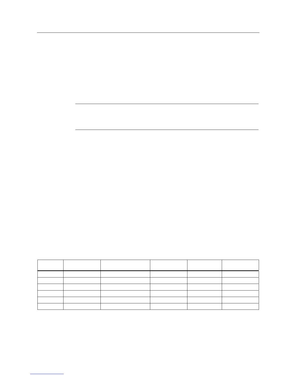
Table 5- 21 Nine Cell Output Filter, Capacitance
Cell Size ZFL @ 4005 V Q, Reactive
@ 60 Hz, 4160 V, 3 Ph
C, Capacitance C %
@ 50 Hz
C %
@ 60 Hz
40 A 57.81 Ohms 25 kVAr 3.83 μF 6.95 8.35
70 A 33.03 Ohms 50 kVAr 7.66 μF 7.95 9.54
100 A 23.12 Ohms 75 kVAr 11.5 μF 8.35 10.00
140 A 16.52 Ohms 100 kVAr 15.32 μF 7.95 9.54
200 A 11.56 Ohms 150 kVAr 22.99 uF 8.35 10.02
260 A 8.89 Ohms 200 kVAr 30.65 uF 8.56 10.28
 Loading...