Product Description
5.3 Cabinet Details
Product User Manual
Operating Instructions, Version AE 12/2009, A5E01454341C
69
4. If Redundant N+1 operation is required, then the transformer size is increased by:
kVA
4
= kVA
3
* 1.125 (3300 V projects)
or
kVA
4
= kVA
3
* 1.08 (6000 V projects)
or
kVA
4
= kVA
3
* 1.25 (N+3, 4160 V projects using 6600 V drive)
or
kVA
4
= kVA
3
* 1.05 (N+3, 4160 V projects using 6600 V drive)
5. Choose the smallest rating greater than or equal to kVA
4
from the applicable frame
size list shown in Chapter 3
1* Excludes long cable provisions
2* Maximum ambient of 50 °C and maximum altitude of 6562 feet
Note:
At elevations above 6562 feet, a dielectric strength derate is required. Consult
engineering.
Fuses
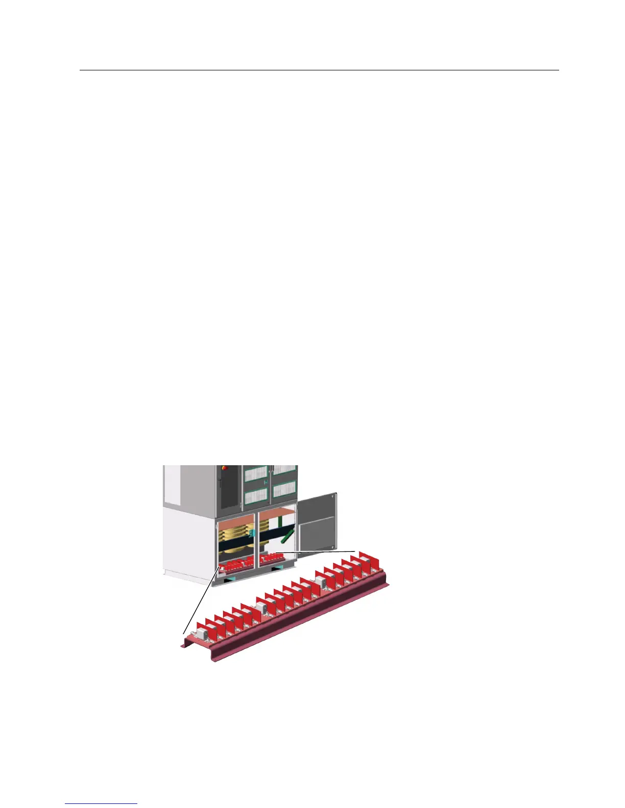
For 4160 V systems, the secondary fuse block is located either in the front of the transformer
section (see Figure "Cut-Out View of Fuse Assembly") or the right hand side of the
transformer cabinet. 6600 V and 10000 V systems have the fuses located on the left hand
side of the cell cabinet behind the front control. There are three approved fuse sources
(Ferraz, Bussmann, and Siba). A label is located on the left side of the fuse block that shows
all approved replacements. Only two phases of each transformer secondary (power cell
input) are fused. Each fuse has visual blown indication, making it easy to diagnose a fuse’s
condition. Fuses are forced air cooled for longer life and less thermal stress.
Figure 5-9 Cut-Out View of Fuse Assembly
The GenIV fuses are mounted external to the cell. This not only reduces the size of the cell,
but also allows for the fuses to be located in an accessible location. They primarily provide
 Loading...