Product Description
5.3 Cabinet Details
Product User Manual
Operating Instructions, Version AE 12/2009, A5E01454341C
89
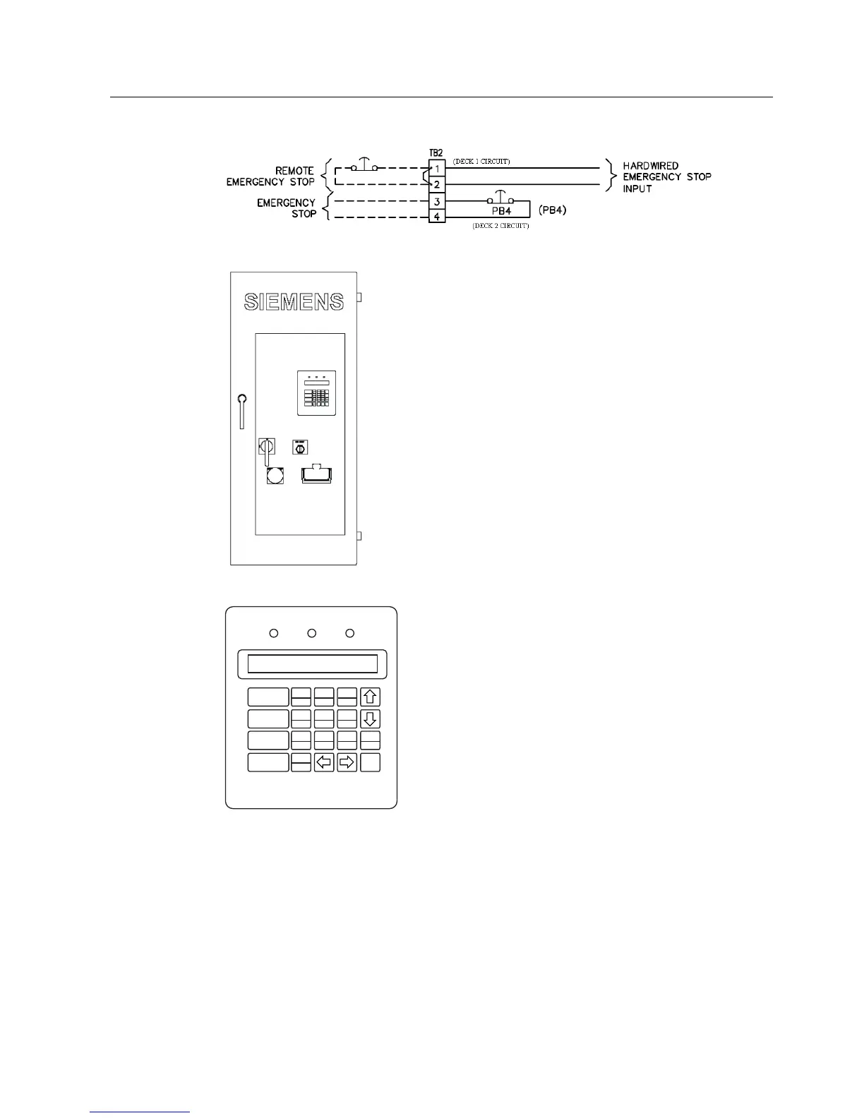
Figure 5-23 E-Stop Circuits (Deck 1 and Deck 2)
.3
'6
3% (1(7
6:
Figure 5-24 Control Door (control arrangement may vary)
32:(521
)$8/75(6(7
$8720$7,&
0$18$/
67$57
0$18$/
6723
'5,9(02725 67$%
$872 0$,1 /2*6
'59352 0(7(5 &200 &$1&(/
(17(5
+(/3
6+,)7
)$8/7 581
6,(0(16
Figure 5-25 Keypad
5.3.5 Upstream Device Ratings
Description
VFDs require an appropriate Input Current Interrupting device installed upstream of the VFD.
This device must be connected between the power source (input line) and the VFD input
 Loading...