Application and Operation
6.14 Cell Bypass
Product User Manual
148 Operating Instructions, Version AE 12/2009, A5E01454341C
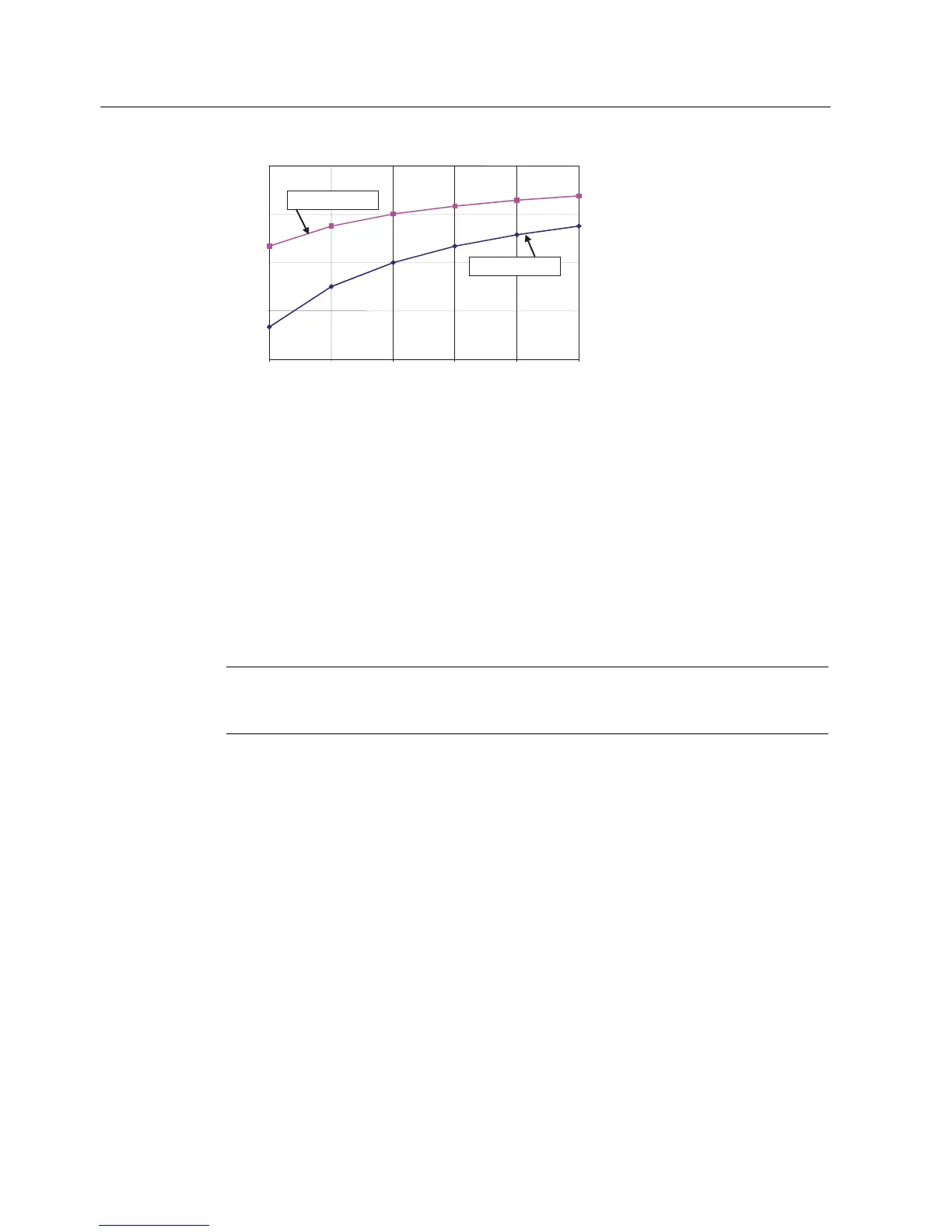
60
70
80
90
100
345678
Original Number of Modules per Phase
Percent of Original Voltage
Available after One Failure
Without Neutral-Shift
With Neutral-Shift
Figure 6-23 Available Voltage after One Cell Bypass
The drive control uses the information of faulted cells to automatically calculate the phase
angles of cell voltages to maintain balanced motor voltages. During neutral-shift, each phase
of the drive operates with a different power factor. Under lightly loaded conditions, it is
possible that one or more phases are absorbing real power while the other phase(s) are
delivering power to the motor. To prevent the cell dc-voltage (corresponding to cells that are
absorbing real power) from increasing (and subsequently causing a drive trip condition), the
control automatically enables the "Energy Saver" function. Under light loads, the energy
saver function reduces motor flux sufficiently so that the motor operates with 70% power
factor. At this operating point, the magnetizing and torque components of motor current are
equal, and all cells deliver real power to the motor. As motor load is increased, the motor flux
level is automatically increased to maintain 70% power factor until rated flux (or maximum
possible flux) is achieved. This function ensures that the cells are delivering real power
under all operating conditions.
Note
In Cell Bypass, the drive will invoke Energy Saver under light loads to prevent certain cells
from charging-up.
 Loading...