7SR210 & 7SR220 Installation Guide
Unrestricted ©2018 Siemens Protection Devices Limited Page 23 of 36
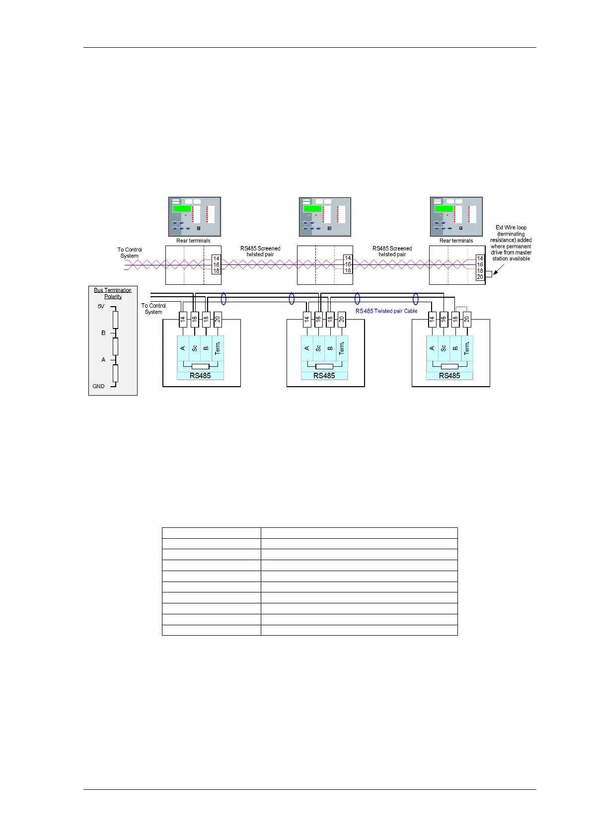
6.4 Additional (Optional) RS485 Connections
The additional (optional) RS485 communication port is located at the rear of the relay and can be connected
using a suitable RS485 120 Ohm screened twisted pair cable.
The RS485 electrical connection can be used in a single or multi-drop configuration. The RS485 master must
support and use the Auto Device Enable (ADE) feature.
The last device in the connection must be terminated correctly in accordance with the master device driving the
connection. The relays are fitted with an internal terminating resistor which can be connected between the A and
B by fitting an external wire loop between terminals 18 and 20 on the power supply module.
Figure 6.4-1 RS485 Data Comms Connections Between Relays
6.5 Additional (Optional) RS232 Connections
The additional (optional) RS232 (9 pin plug) (DTE) communication port is located at the rear of the relay and can
be connected using a suitable RS232 cable.
Where there is a requirement for multi-drop RS232 connection, a suitable device to facilitate this should be
obtained.
3 Transmit Data (TXD)
8 Linked to 7 (volts free)
Figure 6.5-1 RS232 Data Comms Pin Connections
 Loading...


