7SR210 & 7SR220 Commissioning & Maintenance Guide
Page 16 of 82 © 2013 Siemens Protection Devices Limited
V
C
V
B
V
A
I
A
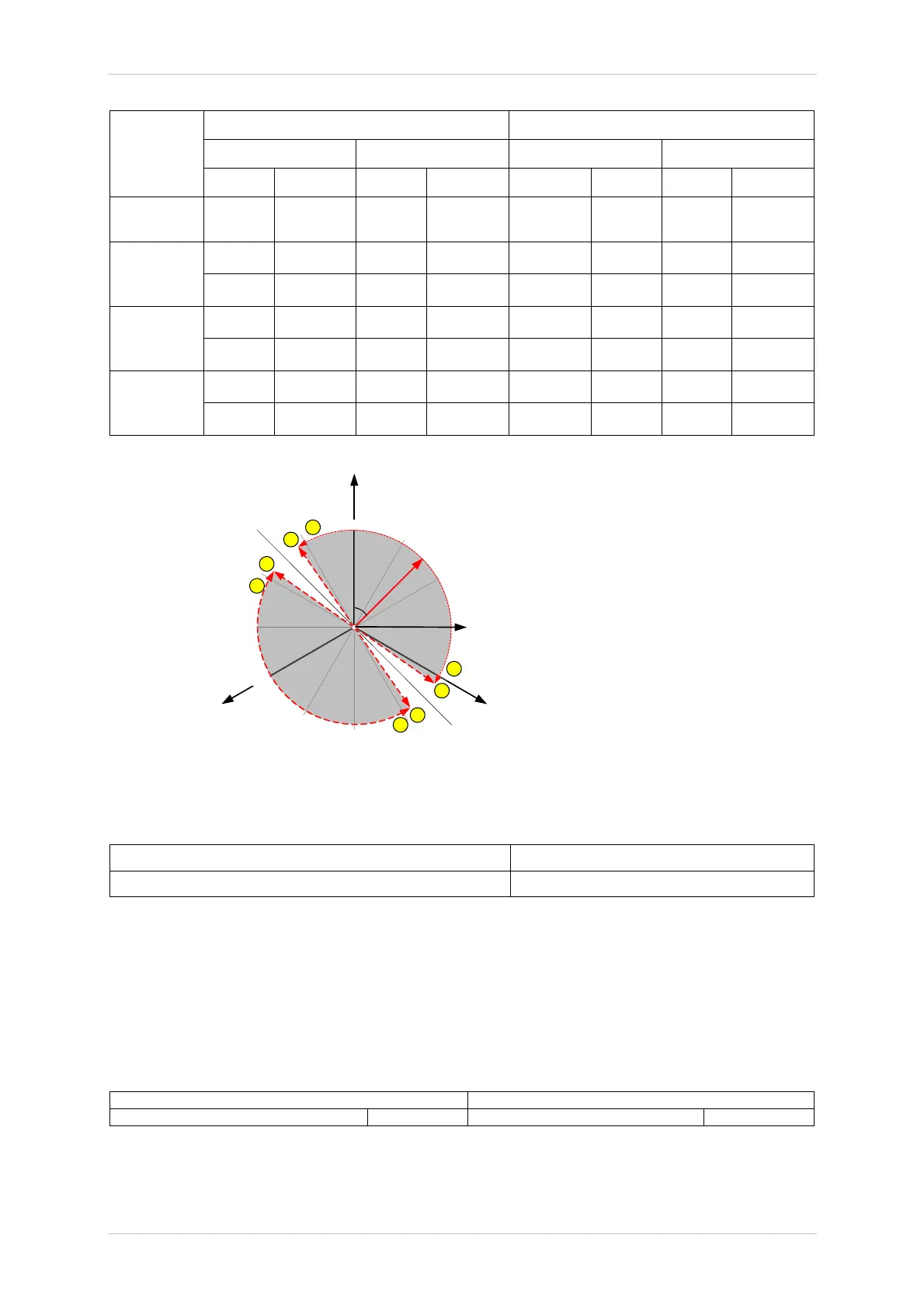
With balanced 3-phase system quantities:
Adjust the phase angle of the currents
relative to the voltages:
Verify directional pick-up and drop off at
points A, B, C and D
Alternatively,
Verify correct directional indication at points
a, b, c and d (C.A +75
0
, +95
0
, -75
0
, -95
0
)
A
B
D
C
a
d
b
c
FWD
REV
+60
0
+30
0
0
0
+270
0
+180
0
+210
0
+240
0
+90
0
V
BC
Forward Reverse
Lag (point C) Lead (point A) Lead(point B) Lag (point D)
Pick-up Drop-off Pick-up Drop-off Pick-up Drop-off Pick-up Drop-off
MTA MTA-85 MTA+85 MTA-85 MTA-85
Phase A
Phase B
Phase C
Figure 2.1-1 Directional Phase Fault Boundary System Angles
4. With the instrument reading ‘Fwd’ or ‘Rev’, reduce the voltage until the element resets. Record the
minimum phase-phase operate voltage.
Minimum Voltage Setting Measured
2.1.1 2 out of 3 logic
Ensure that at least 1 Phase Overcurrent element is set to Directional. Apply balanced nominal voltage. Apply
current at a level above on phase A only at the characteristic angle for forward operation, normally 45º lagging.
Ensure no Directional Phase Overcurrent element operation occurs. Note that non-directional Phase Overcurrent
and Non-direction Earth Fault elements may operate unless disabled.
Repeat the test with Phase A current as above but also with equal current in the B phase at 180º to that in the A
phase.
1 phase current 2 phase current
No 50/51-n Operation 50/51-n operation
 Loading...


