7SR210 & 7SR220 Installation Guide
Unrestricted ©2018 Siemens Protection Devices Limited Page 29 of 36
Section 7: Connection Diagrams
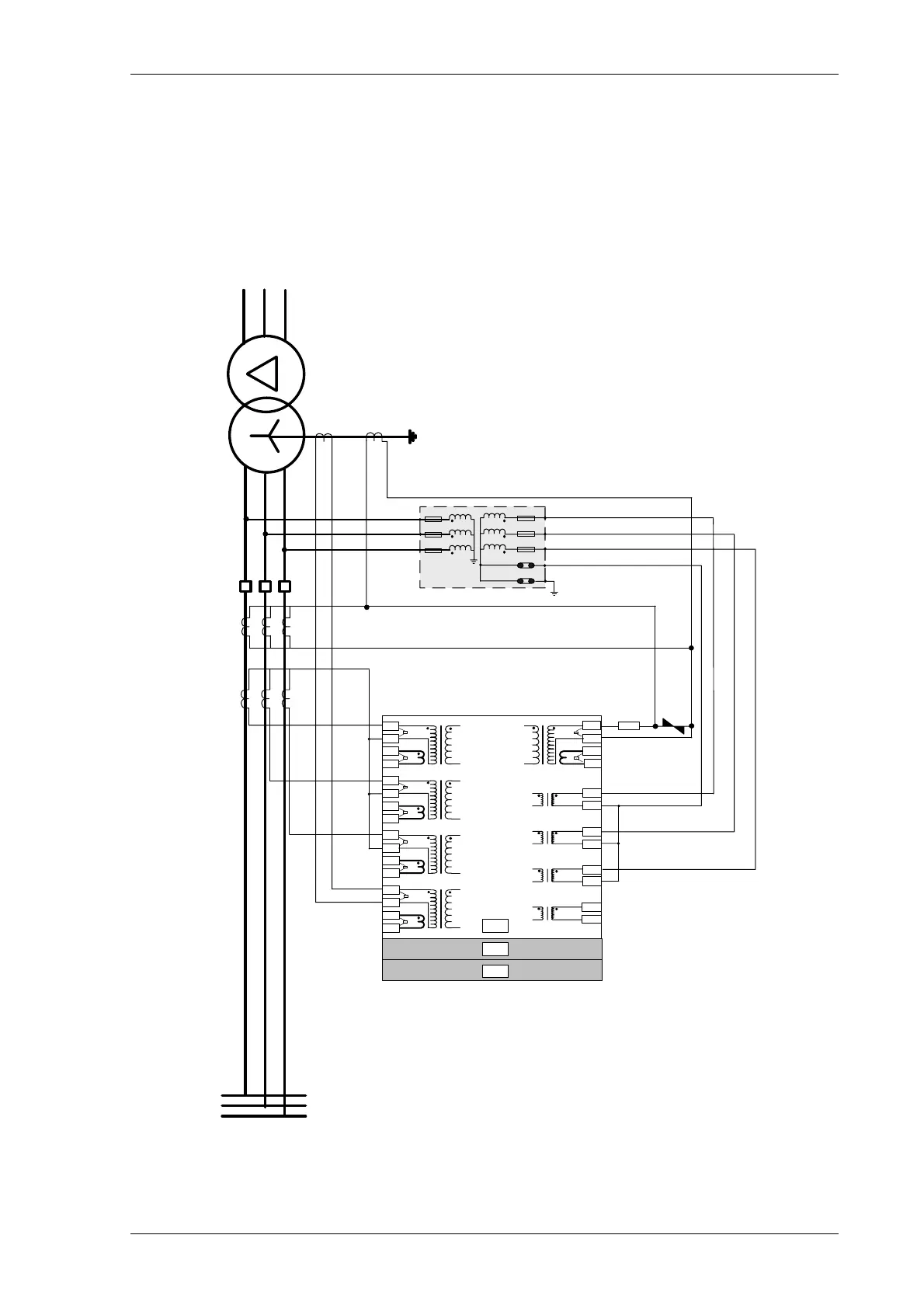
7.1 Typical Connection: 7SR22 Directional OC/EF and REF
I
L1
(I
A
)
1
2
5
6
9
10
13
14
A
17
18
19
20
21
22
23
24
25
26
27
28
1A
5A
1A
5A
1A
5A
1A
5A
15
16
11
12
1A
5A
3
4
7
8
B
C
S1
S2
P2
L1
L2
L3
S1
S2
P1
V
4
(V
X
)
V
L3
(V
C
)
V
L2
(V
B
)
V
L1
(V
A
)
NOTES
1) CT circuits are shown connected to 1 A tap – use alternative tap for 5 A rated CTs.
2) CT and Earth connections are typical only.
3) Application shows use of I
5
as an REF input with external stabilising and voltage limiting resistor.
4) Phase Voltage Config:-V
an
V
bn
V
cn
P2P1
S1 S2 S1 S2
I
L2
(I
B
)
I
L3
(I
C
)
I
4
(I
G
)
I
5
(I
SEF
)
Figure 7.1-1 7SR22 Applied to Transformer Incomer
 Loading...


