138/221
Siemens Switzerland Ltd
User manual RVS61.843 CE1U2355en_02
HVAC Products 6 The settings in detail 23. November 2007
Heat exchanger outside the storage tank, with
primary controller.
The controller calculates the charging pump’s speed
required to ensure that the charging temperature
acquired by sensor B35 is 2 K above the DHW
setpoint. In this case, primary controller sensor B35
must be located in the intermediate circuit.
If B36 is connected as well, B35 must be positioned
as the primary controller sensor. In this case, the
controller calculates the speed required to ensure that
the DHW setpoint + charging increase acquired by
sensor B35 is achieved.
2358A34
B3
Q3
B31
B36
Q33
B35
Speed control of intermediate circuit pump Q33
The controller calculates the speed of the intermediate circuit pump required to ensure
that the return temperature acquired by sensor B36 is 2 K above the DHW setpoint.
If no B36 is connected, sensor B35 is used to make the calculation.
If no valid sensor is connected, the pump speed is not controlled.
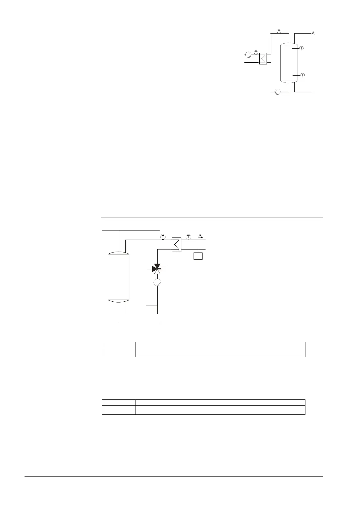
6.17 Instantaneous DHW heater
Summary
2358A31
Y33
Q34
B38B39
FS
The controller supports DHW heating via
an external heat exchanger. The heating
energy required is delivered by the buffer
storage tank.
A speed-controlled or single-speed pump
plus mixing valve are used to supply heat
to the DHW circuit, depending on
demand.
Setpoints
Line no. Operating line
5406 Min setp diff to tank temp
The maximum DHW temperature setpoint controlled is the current storage tank
temperature minus the setpoint differential that can be adjusted here.
Speed-controlled pump
Line no. Operating line
5530 Pump speed min
The minimum speed of the pump for instantaneous DHW heater can be defined. It is
thus possible to negate the lowest pump speeds, which cannot be properly controlled.
Pump speed min
 Loading...


