31/221
Siemens Switzerland Ltd User manual RVS61.843 CE1U2355en_02
HVAC Products 3 Mounting and installation 23. November 2007
Radio connection
Make the radio connection in the vicinity of the RF module prior to mounting so that all
system components are within easy reach.
Prerequisite for the radio link is that all components receive power, which means that
the RF module must be correctly connected to the basic unit and the batteries must be
correctly installed in the room unit.
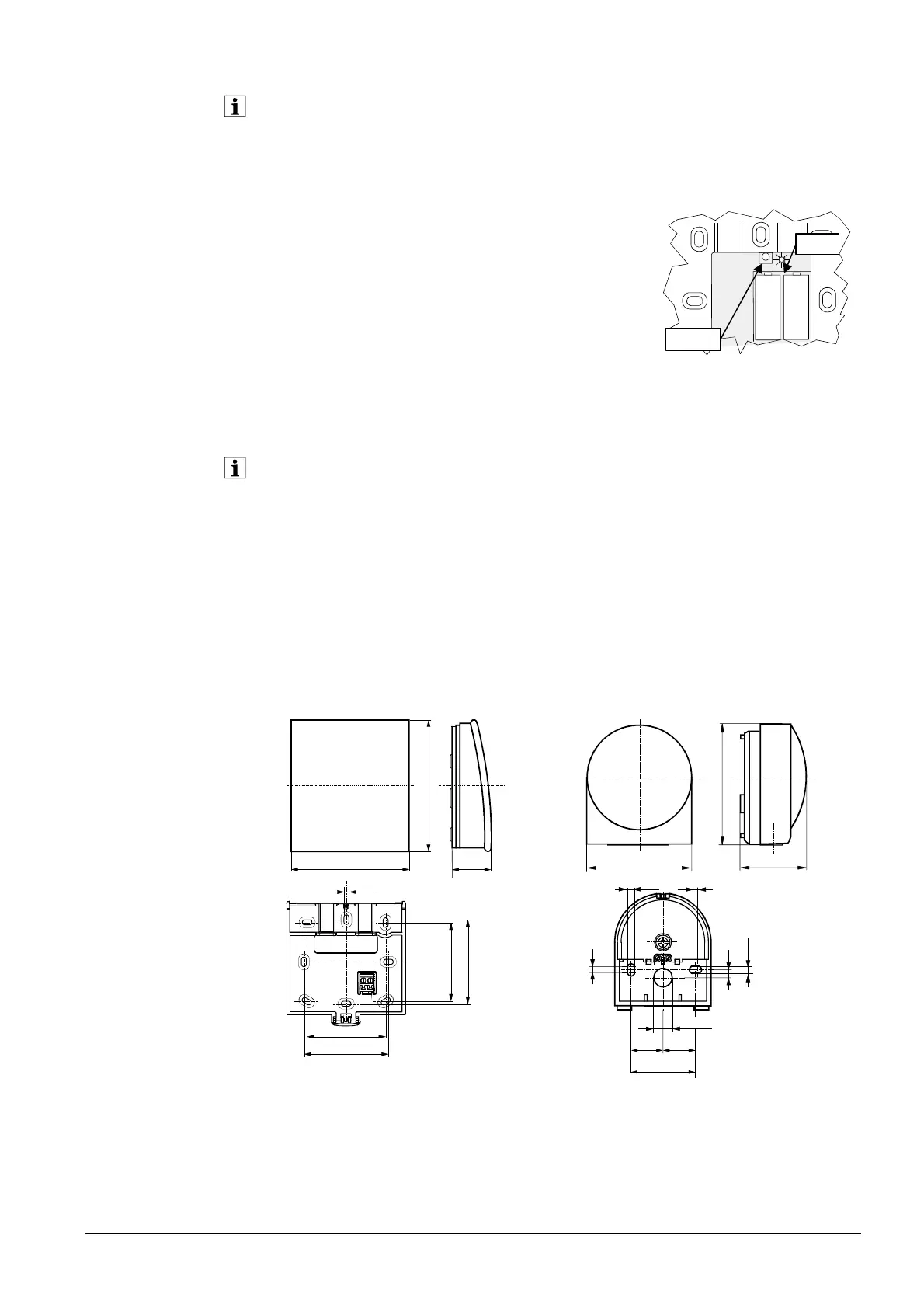
1. Press the button on the RF module for at least 8
seconds until the LED on the RF module starts
blinking at high frequency.
2. Press the button on the transmitter of the
wireless outside sensor for at least 8 seconds
until that LED also starts blinking at high
frequency.
3. The connection is established when the LED on the RF module extinguishes.
4. Press the button on the transmitter of the wireless outside sensor briefly again
until the LED extinguishes.
The test is made to check the quality of the radio link.
• The test can be aborted by pressing the ESC button
• While the radio link can be opened on the controller, the test should be made at the
location where the room unit will be installed
1. Press button 3 on the transmitter of the wireless outside sensor for a maximum
of 8 seconds until the LED starts blinking at low frequency.
2. When radio communication works correctly, the LED on the RF module flashes
briefly at 10-second intervals.
3. After the test, press the button on the transmitter of the wireless outside sensor
again briefly until the LED extinguishes.
Dimensions and
drilling plan
90
100
32
2359Z16
79,8
91,6
49,7
1811M01
12
2359Z27
4,2
56
60
56
60
3
5,5
Ø 14,1
2524,5
49,5
4
5,5
6
1811M02
Establishing the link
Testing
2359Z58
AAA
AAA
LED
Button
 Loading...


