Mounting / Installation
65
Building Technologies A6V10209291_f_en_--
Fire Safety & Security Products 05.02.2010
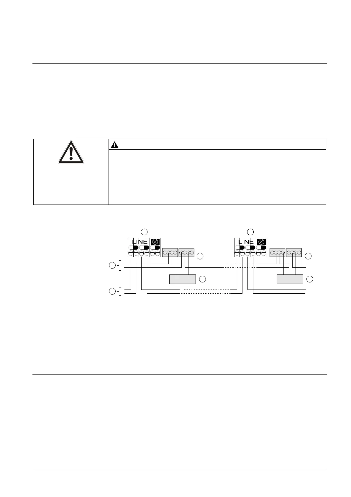
5.9.2 Connection of the detector heating unit
Connect the cables for the monitored supply from the control panel and the
detector heating unit to the supplied micro terminals DBZ1190-AA.
The cables can be placed in the same cable harness as the detector line or
separately.
Several detector heating units can be connected in parallel.
Detector heating units require a separate supply.
WARNING
Openings on detector housing at risk of clogging by snow and ice
This prevents quick and correct detection of a danger status
Check the openings on the housing of the detectors affected on a regular
basis.
Remove snow and ice immediately from the openings on the housing.
+
-
+
-
+
-
+
-
DBZ1190-AA
-
+
LINE
FDBH291
+
-
+
-
+
-
-
+
FDBH291
-
+
DBZ1190-A
FDB221
FDB221-A
FDB222
FDB221
FDB221-A
FDB222
1
2
1
2
33
4
5
Connection diagram for detector heating unit FDBH291
1 Detector base 4 Control panel
2 Micro terminals 5 Control panel supply (monitored)
3 Detector heating unit
5.10 Protective cages
Protective cage DBZ1194 protects the detector against mechanical damage.
EMC-protective cage FDBZ294 protects the detector against mechanical damage
and electromagnetic fields.
See also
Protective cage DBZ1194 [ 38]
EMC-protective cage FDBZ294 [ 38]