Installing the Power Module
31 |
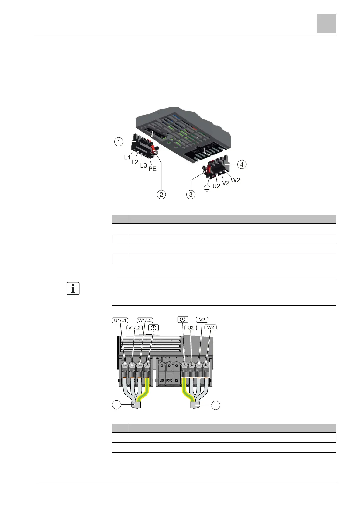
5.3.2 Connecting line and motor terminals
5.3.2.1 Overview of line and motor connections
The following diagrams show the arrangements of the line and motor terminals on
the relevant Power Module of frame sizes FSA to FSF. The permissible tightening
torques for terminals are listed in the table titled "Overview of tightening torques".
Figure 8: IP20 FSA-FSC
1
Detachable mains connector
2
Release lever
3
Release lever
4
Detachable motor connector
The Power Modules are equipped with two-part connectors. You can remove the
detachable part of the connector from the Power Module by pressing the
unlocking device. The connectors cannot be mixed up.
Figure 9: IP20 FSD-FSF
1
Power supply
2
Motor connection

 Loading...


