Installing the Power Module
33 |
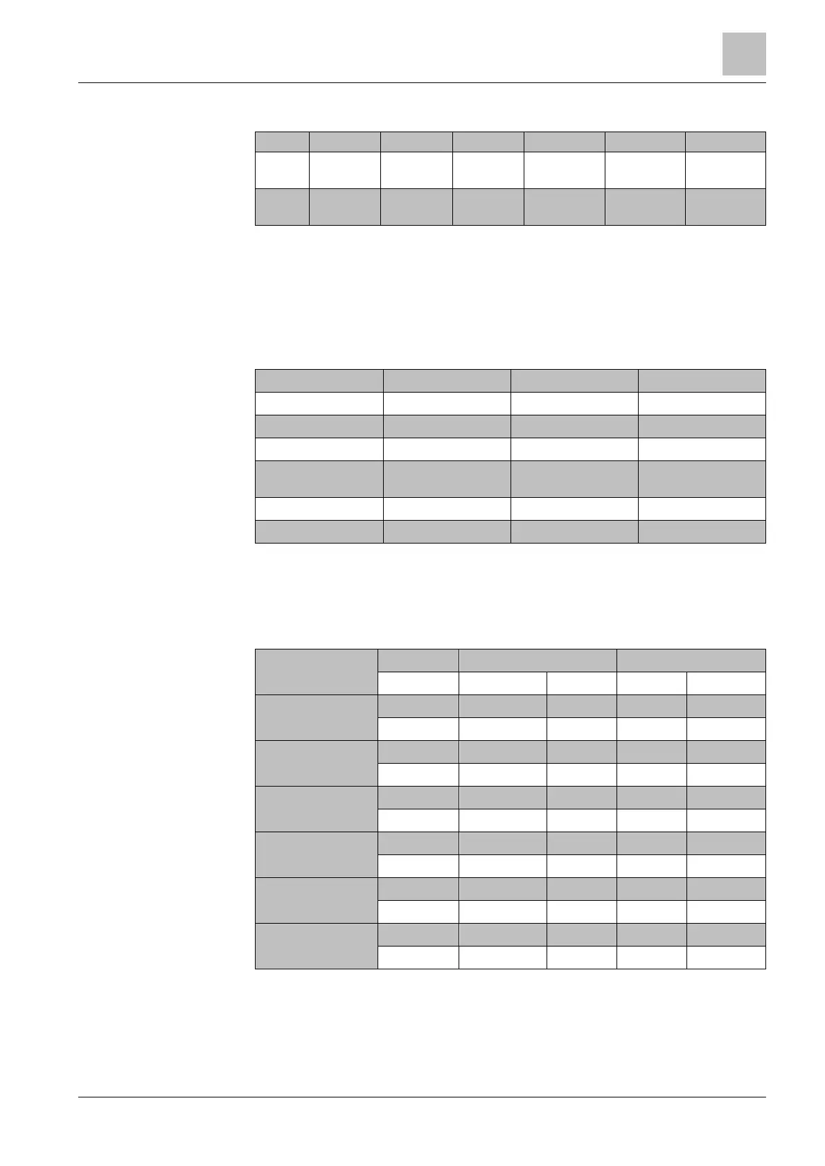
Overview of tightening torques
IP20 0.4 Nm...
0.5 Nm
0.55 Nm...
0.6 Nm
1.2 Nm...
1.5 Nm
6 Nm 6 Nm 13 Nm
IP55 0,5 Nm
(4,4 lbf.in)
0,6 Nm
(5,3 lbf.in)
1,5 Nm
(13,3 lbf.in)
M6: 6 Nm
(53,0 lbf.in)
M6: 6 Nm
(5,3 lbf.in)
M8: 13 Nm
(115 lbf.in)
Table 7: Overview of tightening torques
5.3.2.2 Overview of motor cable lengths and cross sections
The following tables contain all relevant information about required cable lengths
and cross sections. Adherence to the specified values is essential in order to
ensure that the installation complies with EMC regulations.
Shielded C2 25 m (80 ft)
Shielded C3 50 m (164 ft)
Unshielded No 100 m (330 ft)
Shielded C1
(conducted only)
25 m (80 ft) with IP54
50 m (164 ft) with IP20
Shielded C2 50 m (164 ft)
Unshielded No 100 m (330 ft)
● You may only use copper wire of class 1, 75 °C (for compliance with the UL in
frame sizes A to C).
● Ensure that the appropriate circuit breakers or fuses with the specified current
rating are connected between the power supply and the drive.
2
0.37...1.5 1.0 … 2.5 18…14 0.5 4.4
2.2...3 1.5…2.5 16…14 0.5 4.4
4 2.5…6.0 14…10 0.6 5.3
5.5...7.5 4.0…6.0 12…10 0.6 5.3
11 6.0 … 16 10 … 5 1.5 13.3
15...18.5 10 … 16 7 … 5 1.5 13.3
22.0...30 10...35 5...2 6 53
37 25...50 3...2 6 53
45 35...50 2...4/0 6 53
55 70...120 2/0...4/0 13 115
75...90 95...120 3/0...4/0 13 115
0.37...1.5 1.0 … 2.5 18…14 0.5 4.4
Cross sections of power
cables

 Loading...


