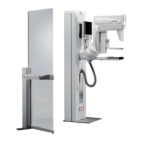
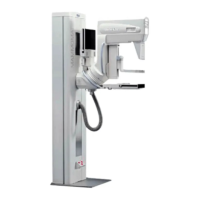
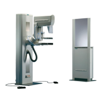
MAMMOMAT
Novation
DR
SPB7-250.815.02 Page 6 of 20 Siemens AG
System Rev. 02 09.04 CS SD 24 Medical Solutions
9 - 6 Image Quality
3. Adjust the grid switch so it will active and deactivate on either edges of the slits
(see Fig. 5 and Fig. 6). You’ll hear a click when the switch activates or
deactivates.
4. Fasten the three screws.
5. Move the grid to the other end position and check that the grid switch activates/
deactivates on either edge of the slit (see Fig. 6 and Fig. 5).
Adjust the "wheel" that is mounted on the grid motor
A wheel is mounted on the left side of the grid motor (M1), on the wheel there is a slits
which activates the grid switch (S1).
1. Move the grid to the left end position.
Fig. 5 Adjust grid switch on edge 1
Fig. 6 Adjust grid switch on edge 2

 Loading...

