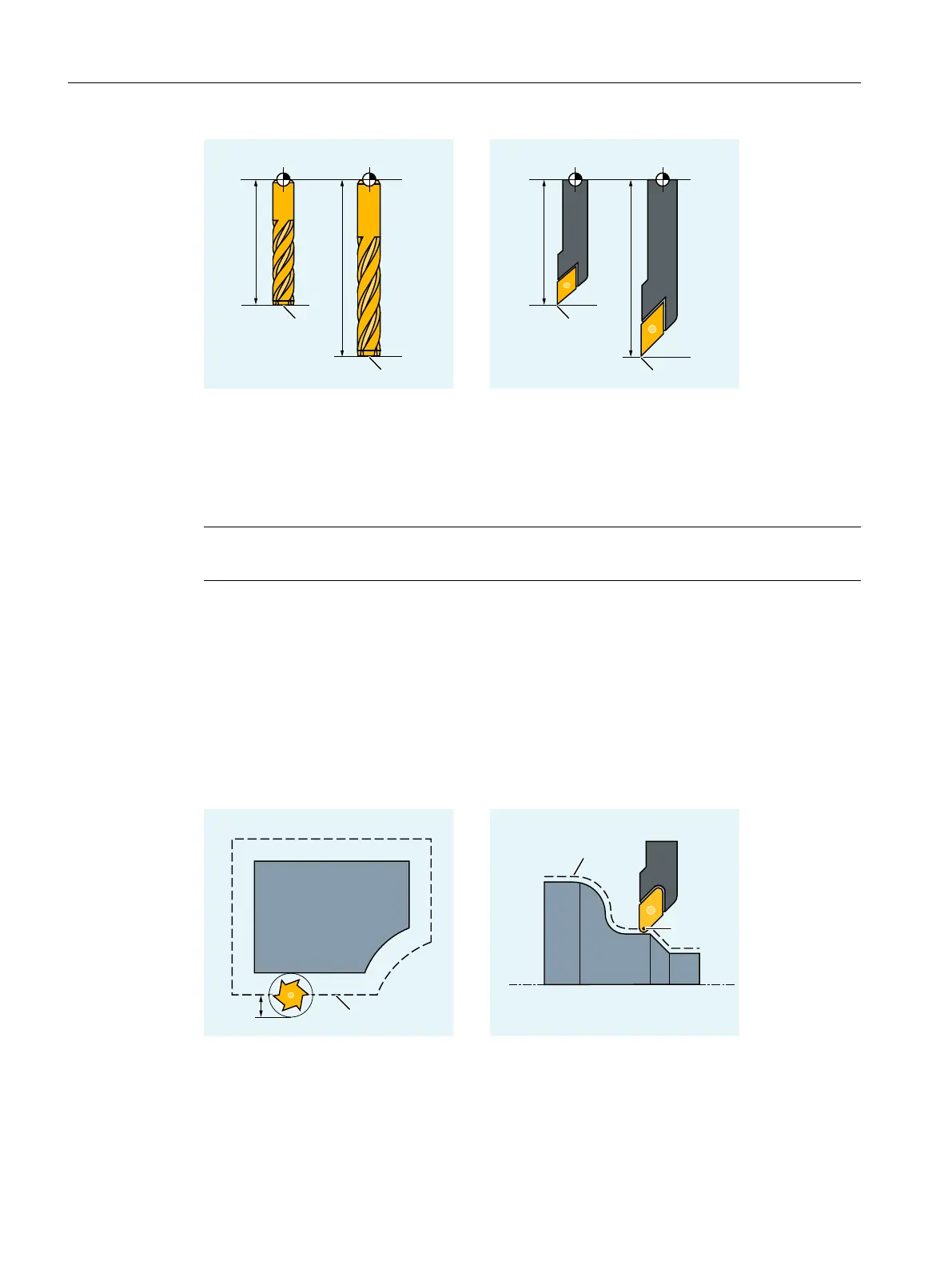
T Tool carrier reference point
P Tool tip
This length is measured and entered in the tool compensation memory of the control together
with definable wear values. From this data, the control calculates the traversing movements in
the infeed direction.
Note
The correction value of the tool length depends on the spatial orientation of the tool.
2.5.3 Tool radius compensation
The contour and tool path are not identical. The milling tool or cutting edge center point must
travel along a path corresponding to the tool radius that is equidistant from the contour (tool
center point path). To do this, while executing the program, the control shifts the programmed
tool center point path – based on the radius of the active tool (tool offset memory) – so that the
tool cutting edge traverses precisely along the programmed contour.
R Tool radius
S Cutting edge center point
The tool radius compensation is described in detail in the "Tool radius compensation
(Page 251)" Chapter.
Fundamentals
2.5 Tool offsets
NC programming
68 Programming Manual, 12/2019, 6FC5398-2EP40-0BA0
 Loading...


