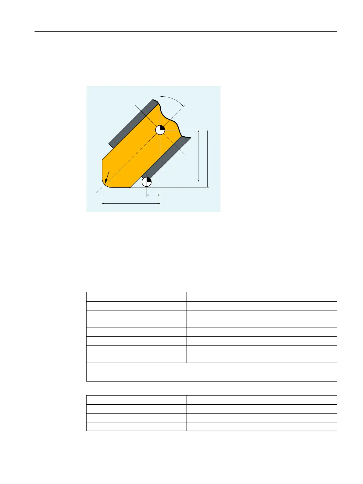
Tool parameters
The following diagram provides an overview of which grinding tool parameters are entered in
the compensation memory:
T Tool carrier reference point
T' Tool holder reference point
L1 Geometry - length 1
L1' Base dimension - length 1
L2 Geometry - length 2
L2' Base dimension - length 2
R Radius
α Angle of inclined wheel
Cutting edge-specific parameters Meaning
$TC_DP1 Tool type 4xy
$TC_DP2 Cutting edge position
$TC_DP3 Geometry length 1
$TC_DP4 Geometry length 2
$TC_DP6 Radius
$TC_DP21 Base dimension length 1
$TC_DP22 Base dimension length 2
● Wear values corresponding to the requirements.
● Set other values to 0.
Tool-specific parameters Meaning
$TC_TPG1 Spindle number
$TC_TPG2 Chaining rule
1)
$TC_TPG3 Minimum wheel radius
Fundamentals
2.5 Tool offsets
NC programming
Programming Manual, 12/2019, 6FC5398-2EP40-0BA0 75
 Loading...


