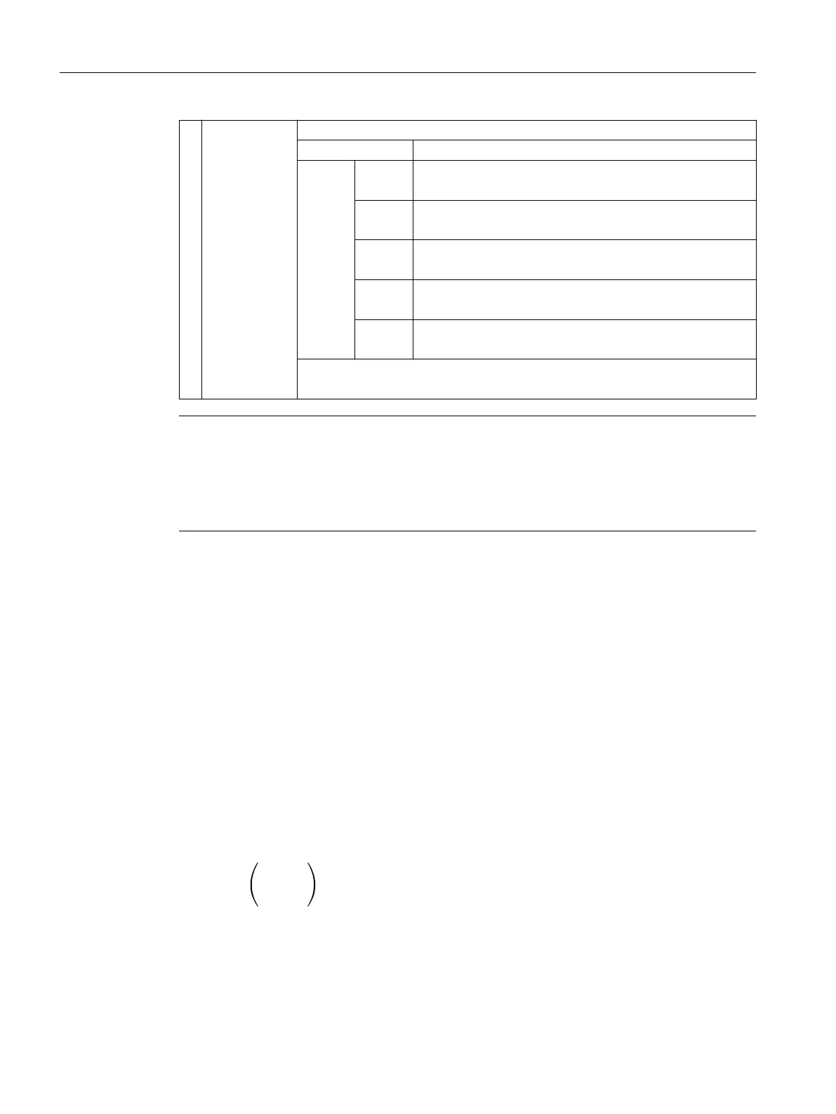
3 <Coord>: coordinate system applicable for the assignment (optional)
Data type: STRING
Charac‐
ters:
MCS
M
The tool length is represented in the machine coordinate
system.
BCS
B
The tool length is represented in the basic coordinate system.
WCS
W
The tool length is represented in the workpiece coordinate
system (default setting).
KCS
K
The tool length is represented in the tool coordinate system
of the kinematic transformation.
TCS
T
The tool length is represented in the tool coordinate system.
The notation of the characters in the string (upper or lower case) is arbitrary.
If the parameter <Coord> is not specified, then WCS is used (default setting).
Note
In the TCS, all tool length components are always parallel or antiparallel to the axes.
The components can only be antiparallel when mirroring is active and the following setting data
is activated:
SD42900 $SC_MIRROR_TOOL_LENGTH (sign change tool length when mirroring)
Example
Standard application, milling tool for G17.
L1 applies in Z (applicate), L2 applies in Y (ordinate), L3 applies in X (abscissa).
Function call in the form:
<Status>=LENTOAX(<AxInd>,<Matrix>,"WCS")
The result parameter <AxInd> then contains the values:
<AxInd>[0] = 3
<AxInd>[1] = 2
<AxInd>[2] = 1
Or, in short: (3, 2, 1)
In this case, the associated matrix (<Matrix>) is:
A change from G17 to G18 or G19 does not alter the result, because the assignment of the
length components to the geometry axes changes in the same way as the assignment of the
abscissa, ordinate and applicate.
A frame rotation of Z through 60 degrees is now programmed with G17 active, e.g.
Work preparation
3.13 Tool offsets
NC programming
832 Programming Manual, 12/2019, 6FC5398-2EP40-0BA0
 Loading...


