Diagnostics and troubleshooting Issue 01/05
CANopen Option Module Operating Instructions
114 6SE6400-5BC00-0BP0
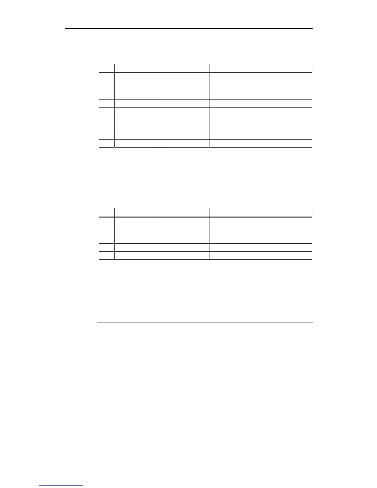
Table 7-2 Status of the red LED display
No. RED part of LED State Description
1 Off No error The device is working normally
2 Single flash Warning limit reached At least one of the error counters of the CAN
controller has reached or exceeded the warning
level (too many error frames).
3 Double flash Error control event A node-guard event
4 Triple flash Sync Error The sync message has not been received with-
in the configured communication cycle period
timeout (see object dictionary entry 1006H).
5 On Bus Off The CAN controller is Bus-Off
Or Fatal Error on option card
6 Blinking Fatal error MICROMASTER specific: Fatal error on Card.
In the CANopen specification the GREEN part of the LED indicates the status of
the CANopen network state machine.
The MICROMASTER 420/430/440 will support the following mandatory states of
the GREEN part of the LED as follows:
Table 7-3 Status of the green LED display
No. GREEN part of LED State Description
1 Off Executing a reset /
Fatal error
The device is executing a RESET
Or (MICROMASTER specific) option module
fatal error
2 Single flash Stopped The device is in the STOPPED state
3 Blinking Pre-operational The device is in the PRE-OPERATIONAL state
4 On Operational The device is in the OPERATIONAL state
Note that the above effects of the two colours in the LED are combined to give a
total status. For example ‘CAN warning limit reached’ during the ‘pre-operational’
state would give a 200 ms flash of the RED LED every second interspersed with a
2.5 Hz signal on the GREEN LED.
NOTE
Orange colour LED is not critical.