Issue 01/05 Diagnostics and troubleshooting
CANopen Option Module Operating Instructions
6SE6400-5BC00-0BP0
113
7 Diagnostics and troubleshooting
A standard combi LED is provided for troubleshooting. This combi LED displays the
module/network status and, alarms generated specifically from the CANopen
module and a diagnostics display parameter.
7.1 LED display
A two-color LED is provided on the front panel of the CANopen module. This
displays the operating status of the module.
An LED test is carried-out when the module is powered-up. The test proceeds as
follows: The LED is lit green for approximately 1 second and then it is red for 1
second and then it goes dark.
The following table explains the various states of the combi LED for the
module/network status.
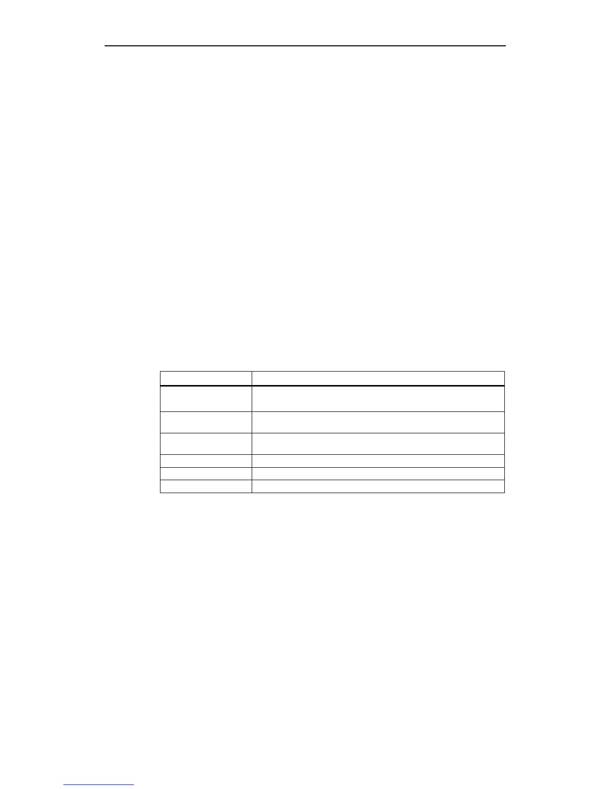
Table 7-1 LEDs display types
LED Action
On LED colour constantly ON
Off LED colour constantly OFF
Flickering iso phase on and off with a frequency of about 10 Hz (approximately
50 ms on / 50 ms off)
Blinking iso phase on and off with a frequency of about 2.5 Hz (approximately
200 ms on / 200 ms off)
Single flash One short 200 ms flash followed by off for 1 s
Double Flash Two short 200 ms flashes followed by off for 1 s
Triple Flash Three short 200 ms flashes followed by off for 1 s
In the CANopen specification the RED part of the LED indicates the status of the
CAN physical layer and indicates errors due to missing CAN messages (SYNC,
NODE-GUARDING, etc).
The MICROMASTER 420/430/440 will support the following mandatory states of
the RED part of the LED and an MICROMASTER 420/430/440 specific option as
follows: