Issue 01/05 Description
CANopen Option Module Operating Instructions
6SE6400-5BC00-0BP0
9
1 Description
The CANopen communications module (CANopen option module) is used to
connect MICROMASTER 420/430/440 drives to higher-level automation systems
with a CAN-bus.
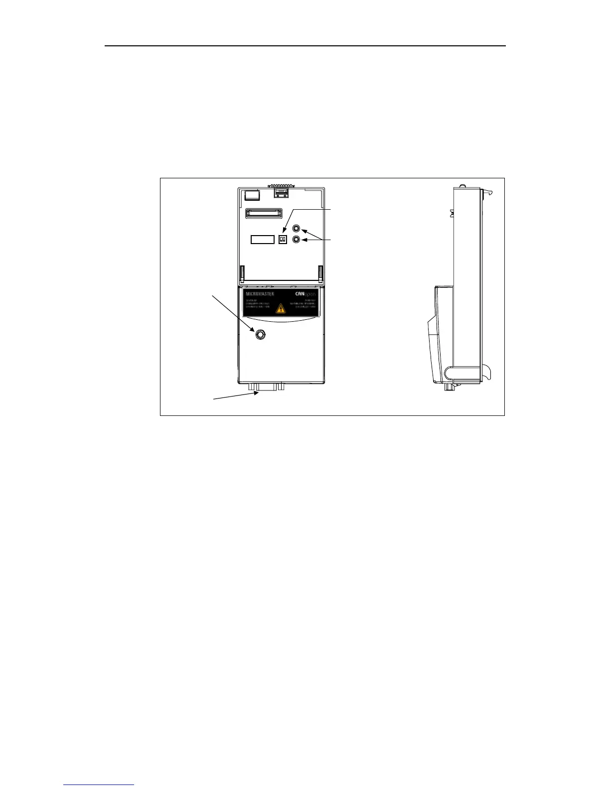
CANopen-/
Module status
LED
12
ON
SUB-D9/
CAN connector
LED Inverter status
see Operating Instructions
for inverter
DIP switch (OFF)
only for internal use
Fig. 1-1 View of the CANopen option module
Technical data
The user can obtain all of the necessary information about the instantaneous
status of the CANopen option module using an LED which displays the status of
both the module and communications. More detailed diagnostics information can
be directly read-out of the diagnostic memory of the CANopen option module using
the diagnostics parameters.
The CANopen option module uses a 9-pin sub-D connector to connect to the CAN
bus system.
The following baud rates are supported: 10, 20, 50, 125, 250, 500, 800 kbaud and
1 Mbaud.