Issue 01/05 Information for the CANopen master
CANopen Option Module Operating Instructions
6SE6400-5BC00-0BP0
107
6.3 Parameter settings for the modes
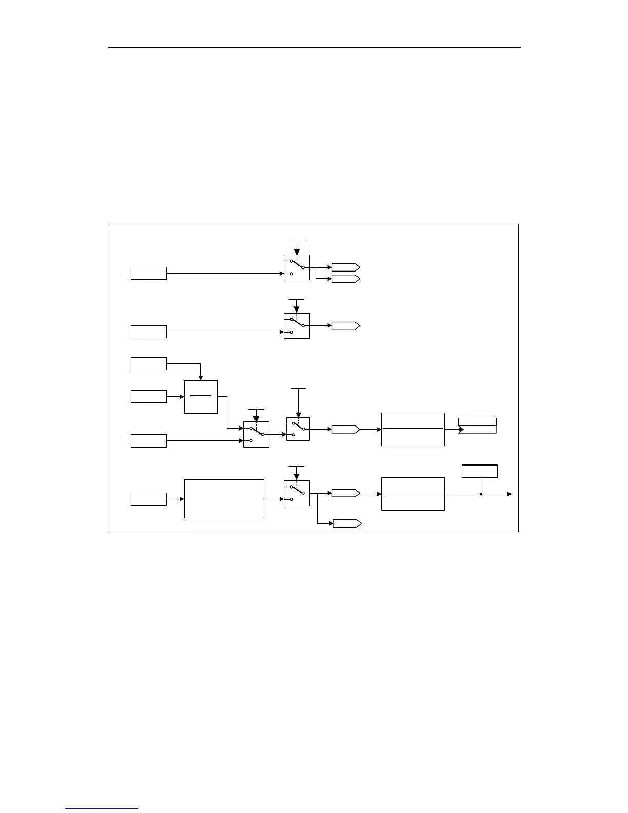
Fig. 6-1 to Fig. 6-4 give an overview to the process data connections and show
appropriate BICO connections for velocity mode and torque profile mode.
6.3.1 Velocity Mode
2802.4H
free object to
MICROMASTER
0
1
RPDO5 P2041.2 bit 03
RPDO6 P2041.3 bit 03
P2050.3
Free connection
2802.3H
free object to
MICROMASTER
0
1
RPDO5 P2041.2 bit 02
RPDO6 P2041.3 bit 02
P2050.2
Free connection
4000H
604EH
604EH
V1_velocity_reference
6052H
V1_nominal_percentage
6042H
V1_target_velocity
P1070 (755.0)
KK
Main Setpoint
0
1
RPDO5 P2041.2 bit 07
RPDO6 P2041.3 bit 07
0
1
RPDO5 P2041.2 bit 01
RPDO6 P2041.3 bit 01
P2050.1
Drive
Frequency Setpoint
BICO connection:
P0700 = 6
Conversion from
CANopen control word
to MICROMASTER
control word
6040H
CANopen
control word
P2050.0
Drive
Control Word
0
1
RPDO5 P2041.2 bit 00
RPDO6 P2041.3 bit 00
r0054
Drive Control Word
r2090
Drive
Control Word
BICO connection:
P0700 = 6
r2091
Fig. 6-1 Process Data transfer from CAN object dictionary to MICROMASTER 420/430/440 using
RPDO5 or RPDO6