Information for the CANopen master Issue 01/05
CANopen Option Module Operating Instructions
72 6SE6400-5BC00-0BP0
The following values must be taken into account for the maximum cable length
between a MICROMASTER and a CANopen-Master with the same values:
CAN interface chip = T
CAN
= In+out 26 ns
Line driver = T
Transceiver
(Tx) = 80 ns
Line driver = T
Transceiver
(Rx) = 150 ns
Opto-coupler = T
Optocouler
= 40 ns
Cable time lag = T
Ltg
= 5 ns/m
Signal propagation time = 0,85
.
T
Bit
=
Baudrate
85,0
(The value 0.85 is permanently set in the MICROMASTER)
This produces the following equation:
Ltg
rOptocouplerTransceiveCAN
T
])T [2Rx]Tx [Tout]In ([T -
Baudrate 2
0,85
⋅++++
⋅
=
m
ns
5
ns]) 40 [2ns] 150 ns [80ns] ([26 -
Baudrate 2
0,85
⋅+++
⋅
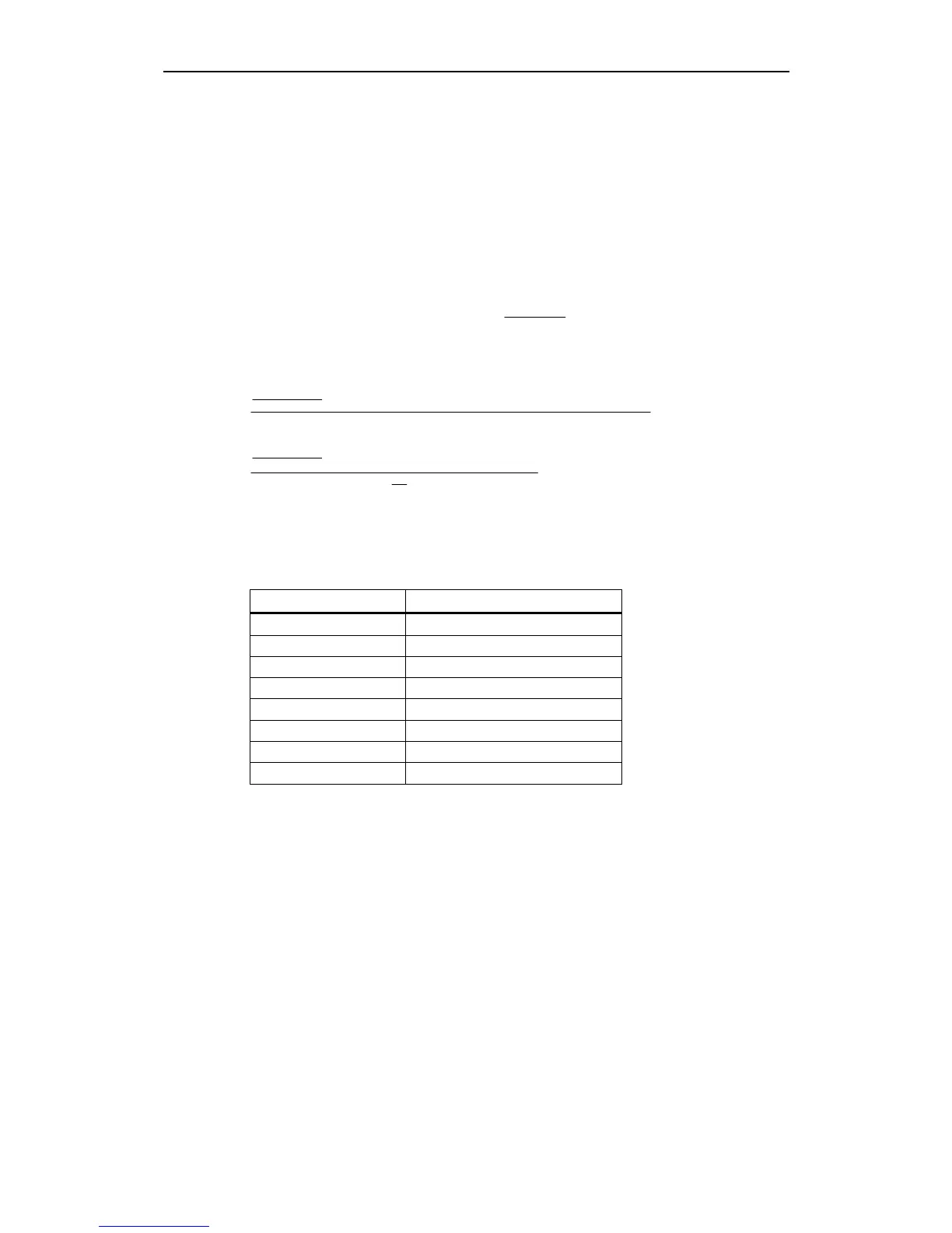
The following approximate cable lengths are obtained from this formula:
Table 4-3 Maximum cable lengths between two bus nodes with the delay times of
MICROMASTER 420/430/440
Baud rate (kbit/s) Maximum network range (m)
1000 18
800 39
500 103
250 273
125 613
50 1633
20 4183
10 8433