(GLWLRQ$ &RQQHFWLRQWR352),%86'3
PROFIBUS Optional Board Operating instructions
6SE6400-5AK00-0BP0
35
%XVWHUPLQDWRU
Each bus segment must have a resistor network, i.e. a bus terminator, at both
ends.
Where the recommended bus connectors have been used, the bus terminator can
be switched in and out by means of switches.
on
off
on
off
Terminating resistor
switched in
Terminating resistor
QRW
switched in
Fig. 4-3 Switch positions for activated or deactivated bus terminating resistors
If these bus connectors are not installed, the user must ensure that a bus
terminating network is installed on the first and last bus nodes as specified in the
diagram below.
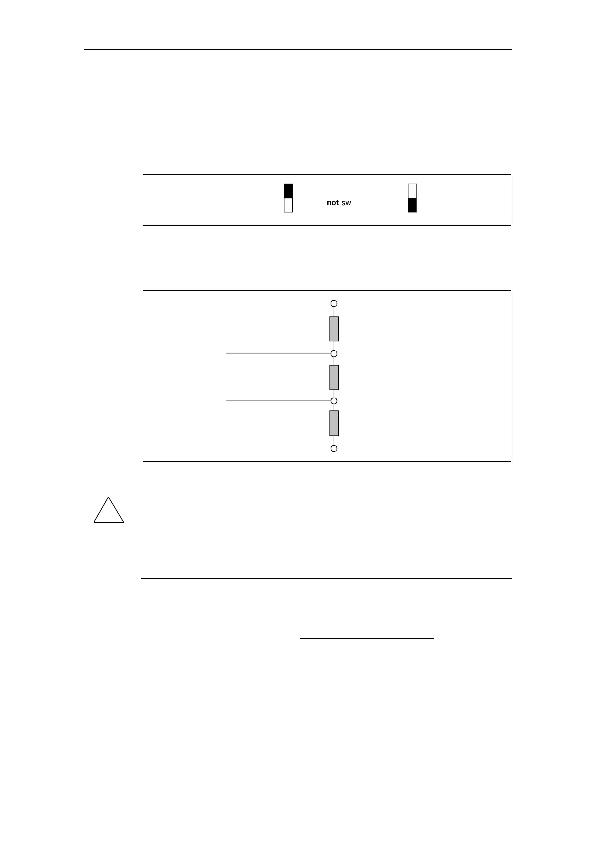
Data cable
Data cable
VP (PIN 6)
390 ohms
RxD/TxD-P (PIN 3)
220 ohms
RxD/TxD-N (PIN 8)
390 ohms
DGND (PIN 5)
Fig. 4-4 Bus terminating network
:$51,1*
A bus segment must always be terminated at both ends by a terminating resistor.
This is not the case, for example, if the last slave with bus connector is switched
off, since the bus connector voltage is supplied by the station and the resistor is
thus inoperative.
It must be ensured that all stations on which a terminating resistor is activated are
supplied with power at all times.
5HPRYLQJDEXVFRQQHFWRU
You can remove the bus connector with looped-through bus cable from the
PROFIBUS-DP interface at any time without interrupting the data exchange on the
bus.