(GLWLRQ$ 'HVFULSWLRQRI0,&520$67(5352),%862SWLRQDO%RDUG
PROFIBUS Optional Board Operating instructions
6SE6400-5AK00-0BP0
11
'HVFULSWLRQRI0,&520$67(5352),%86
2SWLRQDO%RDUG
The function of the PROFIBUS-DP communication board (PROFIBUS optional
board) is to provide a PROFIBUS-DP-based link between drives of the
MICROMASTER4 product range and higher-level automation systems.
9
8
1
2
3
4
5
6
7
ON
1234567 12
ON
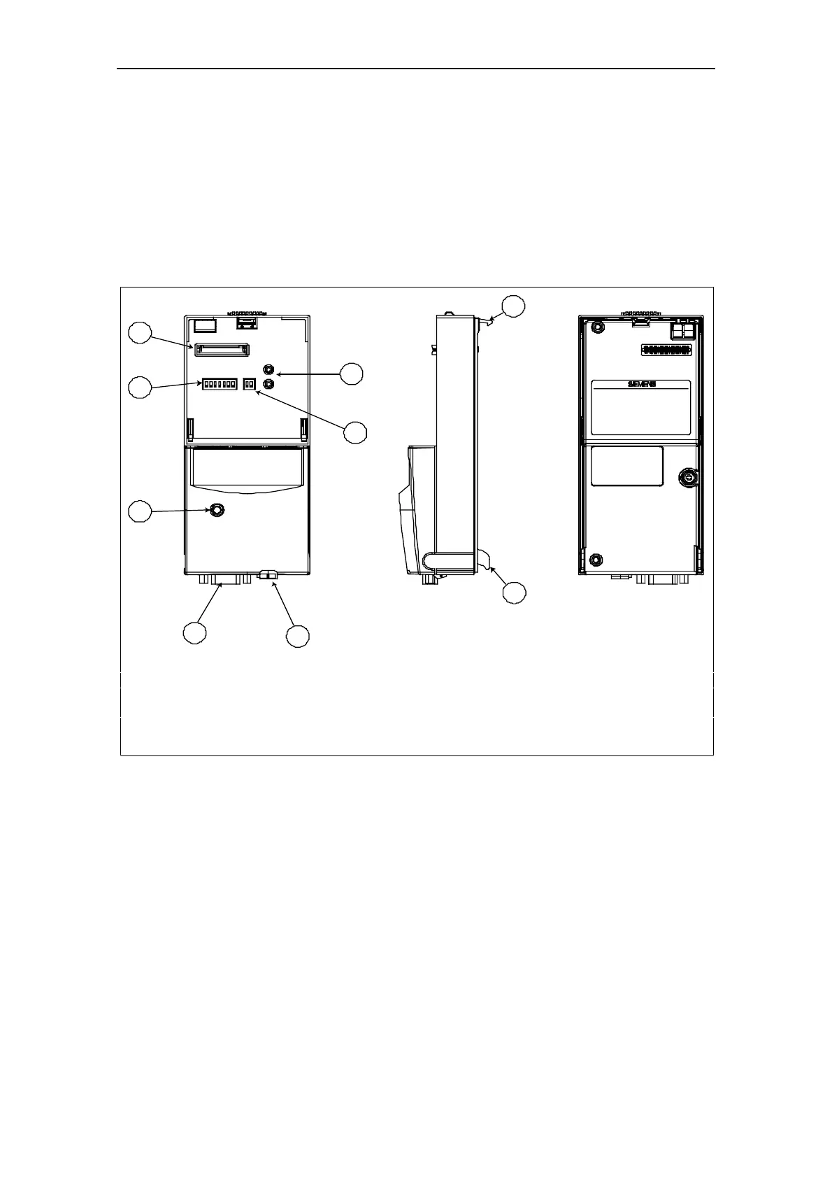
1 Contact connector for control unit 6 (for Siemens internal use only)
2 PROFIBUS address switch 7 Operating status display for MICROMASTER4
3 Operating status display for PROFIBUS board 8 Latching mechanism
4 PROFIBUS interface 9 Guide
5 Local 24 V connection
Fig. 1-1 View of communication board
7HFKQLFDOGDWD
To display information about the current operating state, the communication board
has a 3-color LED (green, orange, red).
Its voltage is supplied via the converter system connector.
Alternatively, an external 24 V connection can supply the voltage for the
PROFIBUS optional board and converter electronics.
The board is connected to the PROFIBUS system via a 9-pin sub D socket
connector complying with the PROFIBUS standard. All connections to this RS485
interface are short-circuit-proof and isolated.