(GLWLRQ$ 'LDJQRVWLFVDQG7URXEOHVKRRWLQJ
PROFIBUS Optional Board Operating instructions
6SE6400-5AK00-0BP0
53
'LDJQRVWLFVDQG7URXEOHVKRRWLQJ
There are three types of diagnostic display:
½ LED
½ Alarm numbers
½ Diagnostic parameter
'LDJQRVWLFVXVLQJ/('GLVSOD\
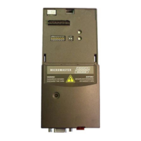
The three-colored LED display is on the front panel of the PROFIBUS-DP
communication board. It provides instantaneous information about the status of the
board.
Possible LED displays are explained in the table below.
Table 7-1 LED display on PROFIBUS-DP communication board
/(' 'LDJQRVWLFLQIRUPDWLRQ
off No power supply
red, flashing
fast
Invalid PROFIBUS address on DIL switch (126/127 is invalid)
or hardware fault
or software error
red on Startup and no communication (yet) with the converter
or new communication board configuration, after modification of a board
parameter
If this status is steady, then the converter or PROFIBUS optional board is
defective.
orange
flashing
Communication link to converter has been established
No connection to PROFIBUS, e.g. PROFIBUS connector is not inserted or
PROFIBUS master disconnected.
orange on Communication link to converter and connection to PROFIBUS have been
established, but no cyclical data exchange is taking place.
green
flashing
Cyclical process data exchange in progress, but setpoints invalid (control
word = 0), e.g. because SIMATIC master is in "Stop" state
green on Cyclical process data exchange in progress and o.k.
127(
If a class 2 master with acyclical communication (PC or HMI) is installed, but no
class 1 master with cyclical data exchange, then the LED displays "orange on".
 Loading...

