(GLWLRQ$ &RPPXQLFDWLRQZLWK0,&520$67(5YLD352),%86'3
PROFIBUS Optional Board Operating instructions
6SE6400-5AK00-0BP0
25
3.:PHFKDQLVPIRUSURFHVVLQJSDUDPHWHUV
3DUDPHWHUDUHD3.:
Using the PKW mechanism you can process and monitor parameters (write/read)
as described below:
3UHFRQGLWLRQ
PPO type 1 on MICROMASTER4 in accordance with PROFIDrive Profile version
2.0
or
use of acyclical channel in conjunction with data block 100
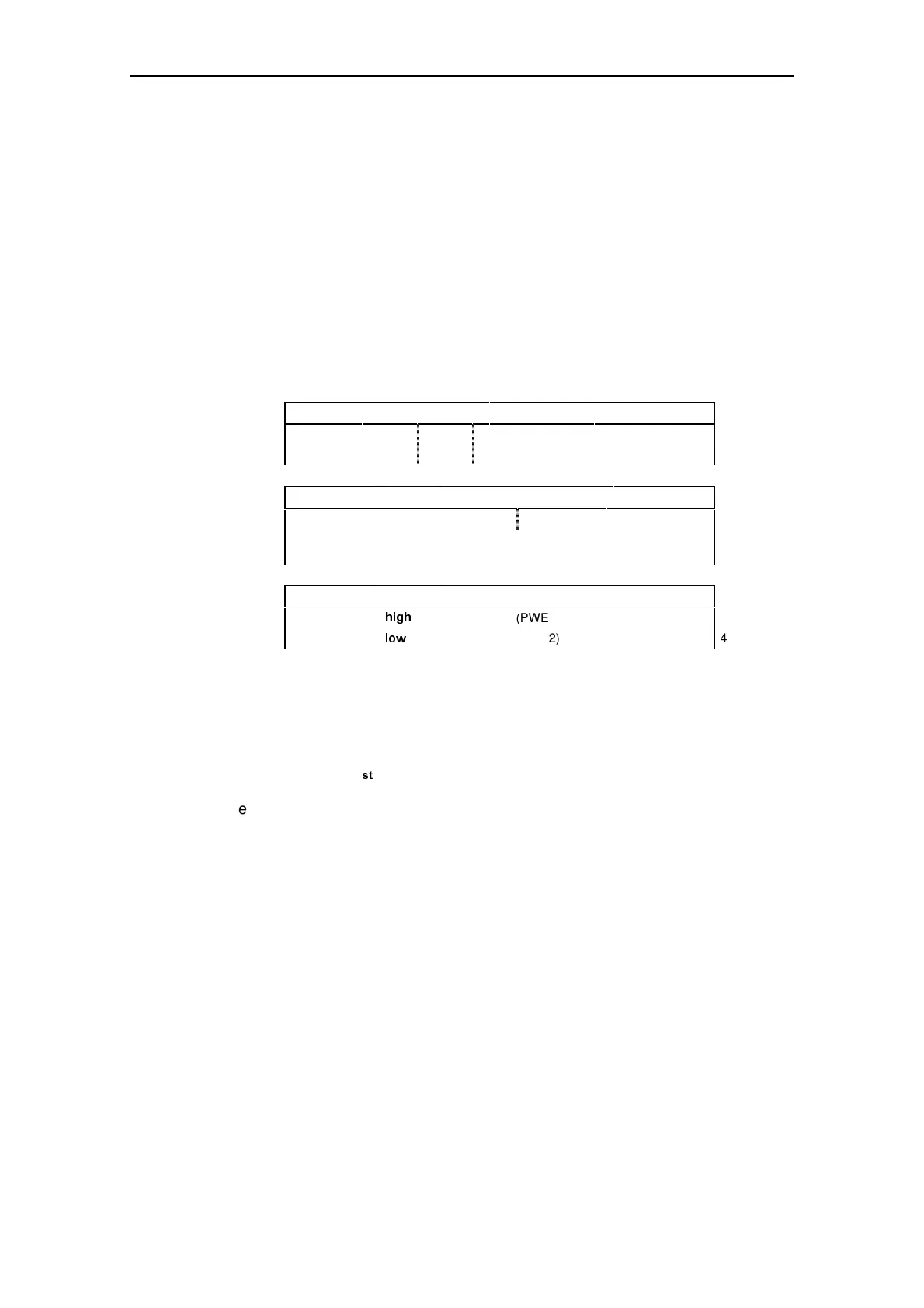
The parameter area includes at least 4 words.
Parameter identifier (PKE) 1
st
word
Bit no.:15 121110 0
AK 0 PNU
Parameter index (IND) 2
nd
word
Bit no.: 15 8 7 0
Structure and meaning are dependent on mode of data exchange used (see
following pages)
Parameter value (PWE)
Parameter value
KLJK
(PWE1) 3
rd
word
Parameter value
ORZ
(PWE2) 4
th
word
AK:
PNU:
Request or response identifier
Parameter number
Fig. 3-4 Structure of parameter area (PKW)
3DUDPHWHULGHQWLILHU3.(
VW
ZRUG
The parameter identifier (PKE) is always a 16-bit value.
Bits 0 to 10 (PNU) contain the number of the relevant parameter.
Bit 11 is reserved.
Bits 12 to 15 (AK) contain the request or the response identifier.
The meaning of the request identifier for request telegrams (master → converter) is
shown in Table 3-3. Request identifiers 11 to 14 are specific to MICROMASTER
and not defined in the PROFIDrive Profile.
The meaning of the response identifier for response telegrams (converter →
master) is shown in
Table 3-4. The request identifier will determine which response identifiers are
possible. If the response identifier is 7 (cannot process request), then one of the
fault numbers listed in Table 3-5 will be stored in parameter value 2 (PWE2).