1-4
Description
Components Of The Basic
System
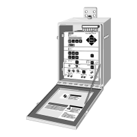
The basic MXL-IQ Control Panel consists
of the following components:
• SMB-2 Main Board
• MPS-6 or MPS-12 Power Supply
• MKB-4 Keyboard/Annunciator
• PAL-1 Logging Printer
(NFPA Proprietary and UL 1076 configu-
rations)
• PIM-1 Peripheral Interface Module
(NFPA Proprietary and UL 1076 configu-
rations)
• PIM-2 Peripheral Interface Module
(NFPA Proprietary and UL 1076 configu-
rations)
• MSE-3L Enclosure
• TSW-2 Tamper Switch
(UL 1076 configuration only)
• BP-61, BTX-1, or BTX-2 Batteries
SMB-2 Main Board
The SMB-2 Main Board contains:
• 16-bit central processing unit (CPU)
• System read-only memories (EPROMs)
• System random-access memory (RAM)
• FLASH memory for CSG-M
• Watchdog circuitry
• Network interface circuitry
• Battery charger
• 24V regulator
• AC transfer relay
• CZM-1B6 auxiliary power
• 24 VDC unregulated supply
• Two analog loops (initiating/control)
• Two notification appliance circuits
(audible circuits)
• Two dry-contact relays (Form C)
Figure 2
SMB-2 Main Board
CB1
NAC1
P14P1
F2
BATTERY
20A
P2
BATTERY
MPS-6 MPS-12
F3
CZM-1B6 POWER
2 AMP
CB2
NAC2
10
11
12
CZM-1B6
POWER
1
P8
TB3
P3
POWER TO MOM-4
2 AMP MAX.
3
4
4
1
2
LOOP 2
NAC 2
NOT
USED
NAC 1
6
6
7
8
9
1
1
2
2
3
3
4
4
5
5
TO ANN-1
P13
GND FAULT
DISCONNECT
TB2
LOOP 1
1
2
3
5
1
2
3
4
12ATOMOM-4
DO NOT USE
MNET
TRBL
I
C
1
1
0
I
C
1
1
1
I
C
1
1
2
I
C
1
1
3
I
C
1
1
4
TB1
PROGRAMMER
P5
S7
S4
P15
OFF ON
P17
1
P10
D2300CP
PRINTER
1
P4
MOM-4
1
P6
1
1111
ALR
F1
MPS-6
8 AMP
F4
MOM-4
15 AMP
SMB-2
 Loading...

