Operating the contactor panel with panel width 435 mm
110-0134.9 / 14 NXAIR / ≤ 40 kA 143
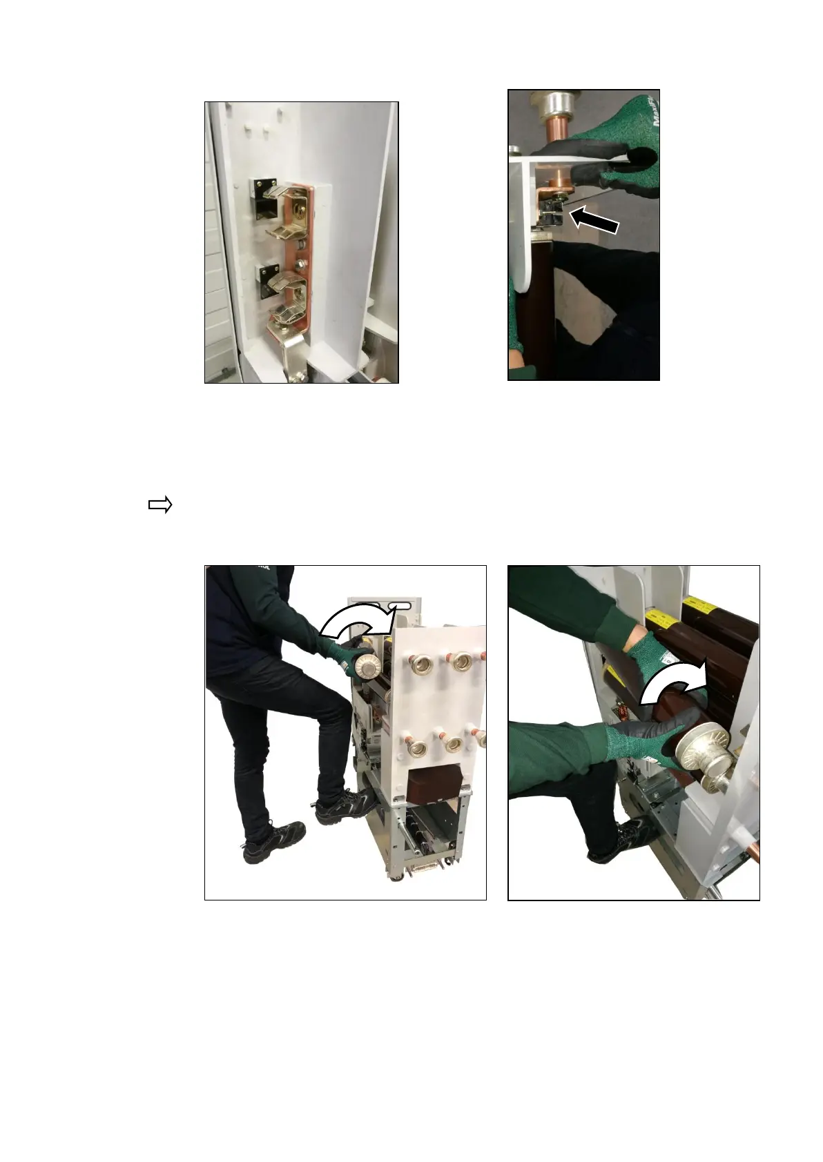
Fig. 249: HV HRC fuse-link removed
in the striker area
Fig. 250: HV HRC fuse-link removed on
the opposite side of the striker
area
Insert the HV HRC fuse-link by turning while pushing it into the clamps. The position of the
striker is identified with a triangle representing an arrow on the rating plate of the HV HRC
fuse-link.
If only one HV HRC fuse-link is to be installed in the phase, use the upper position at the
clamps.
Fig. 251: Inserting the HV HRC fuse-link
in the striker area
Fig. 252: Inserting the HV HRC fuse-link
on the opposite side of the
striker area

 Loading...


