Operating the contactor panel with panel width 435 mm
144 NXAIR / ≤ 40 kA 110-0134.9 / 14
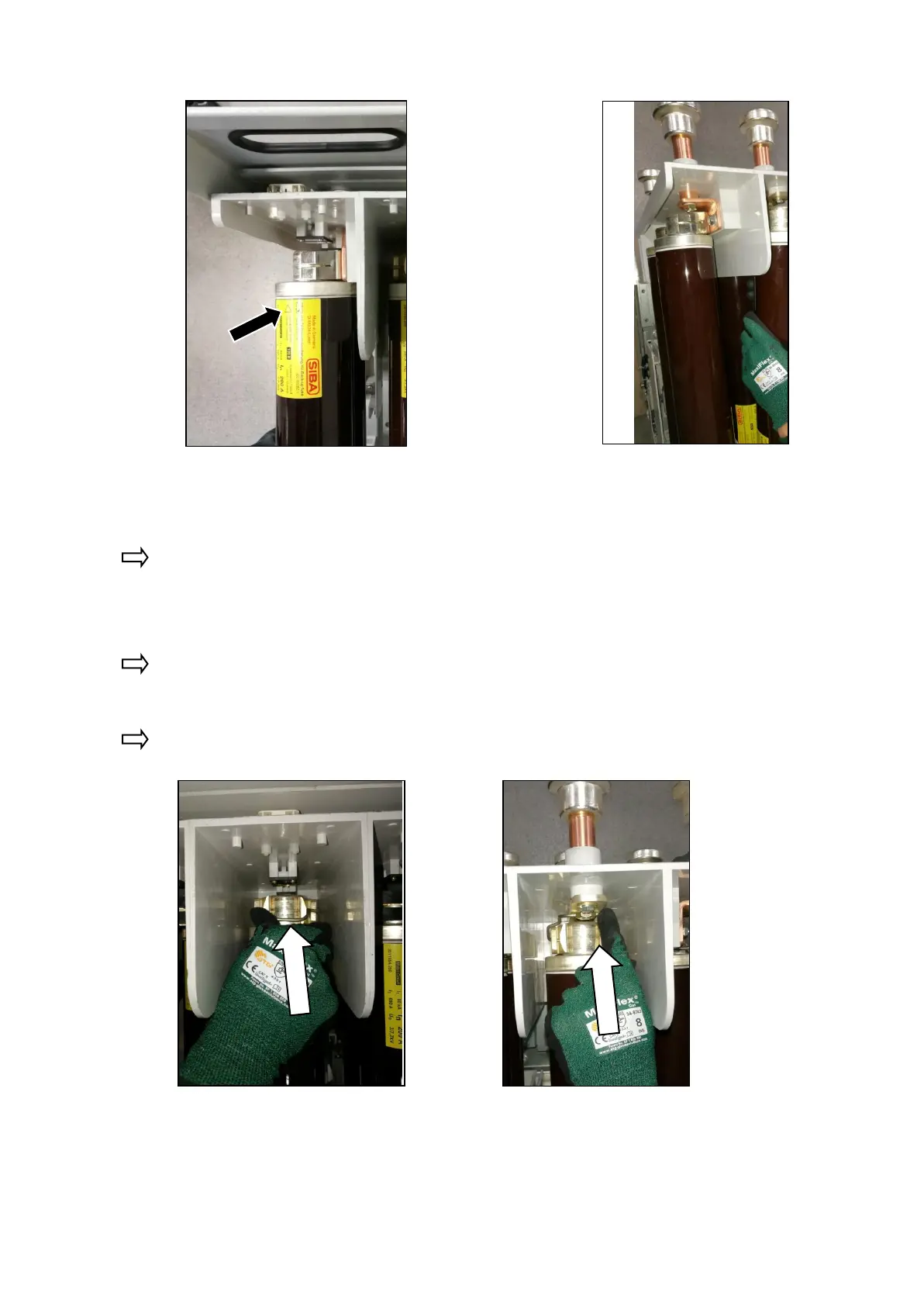
Fig. 253: HV HRC fuse-link inserted and
fuse -link bracket closed in the
striker area
Fig. 254: HV HRC fuse-link inserted and
fuse-link bracket closed on the
opposite side of striker area
Proceed in the same way with the other HV HRC fuse-links at the L1 and L3 phases.
After removing the HV HRC fuse-links from the outer phases L1 or L3, the fuse-links in the
middle phase L2 are accessible from the right or left side of the contactor truck.
Open both fuse-link brackets of the phase manually or with a suitable tool, for example a
screwdriver.
First remove the upper HV HRC fuse-link by pulling it upwards out of the clamps. If a second
lower fuse-link is installed in the phase, remove it too.
Fig. 255: Opening the fuse-link bracket in
the striker area (operating side of
contactor truck)
Fig. 256: Opening the fuse-link bracket on
the opposite side of striker area
(contact tulip side of contactor
truck)

 Loading...


