Operating the contactor panel with panel width 435 mm
110-0134.9 / 14 NXAIR / ≤ 40 kA 145
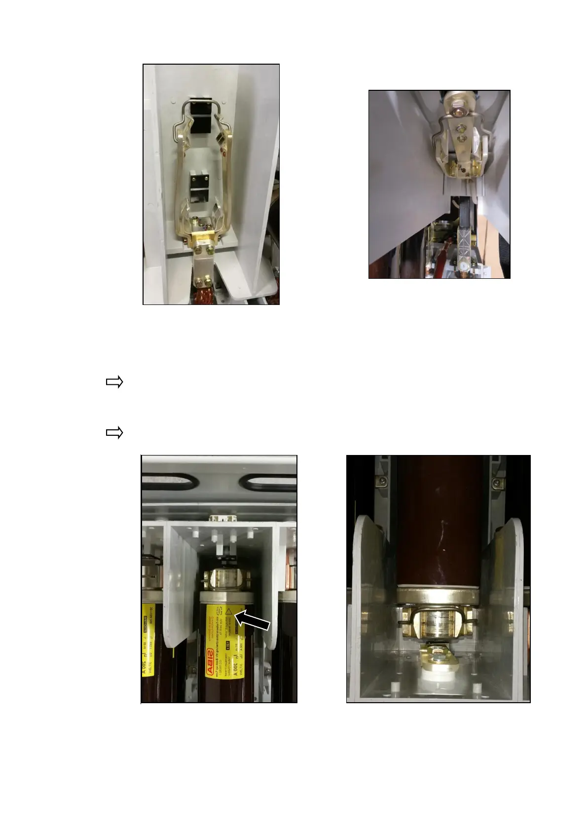
Fig. 257: HV HRC fuse-link removed in the
striker area
Fig. 258: HV HRC fuse-link removed on the
opposite side of the striker area
Insert the HV HRC fuse-link with the striker pointing to the operating side of the contactor
truck. The position of the striker is identified with a triangle representing an arrow on the
rating plate of the HV HRC fuse-link.
If only one HV HRC fuse-link is to be installed in the phase, use the upper position at the
clamps.
Close both fuse-link brackets.
Fig. 259: HV HRC fuse-link inserted and
fuse -link bracket closed in the
striker area
Fig. 260: HV HRC fuse-link inserted and
fuse-link bracket closed on the
opposite side of striker area
The HV HRC fuse-links have been replaced.

 Loading...


