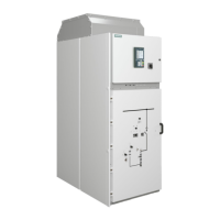
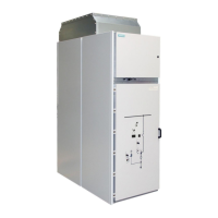
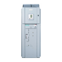
Operating the contactor panel with panel width 600 mm
110-0134.9 / 14 NXAIR / ≤ 40 kA 191
Fig. 342: Front side of contactor truck:
Indicator for HV HRC fuse-links
Fig. 343: High-voltage door:
Indicator for HV HRC fuse-links
Arrangement of HV HRC fuse-links
Depending on the panel version, contactors are equipped with either single or double fuse-link arrangement
per phase. Hereafter, replacing HV HRC fuse-links is shown using the example of a double fuse-link
arrangement.
When replacing a single fuse-link arrangement, proceed in an analogous way.
Rear side of contactor truck
Middle phase L2 with double
fuse-link arrangement
Outer phase L3 with double
fuse-link arrangement
Right side of contactor truck
Front side of contactor truck
Left side of contactor truck
Outer phase L1 with double
fuse-link arrangement
Fig. 344: Seen from top: Arrangement of HV HRC fuse-links
(example with double fuse-link arrangement)

 Loading...


