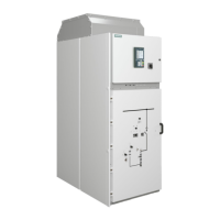
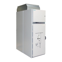
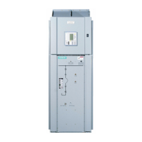
Operating the contactor panel with panel width 600 mm
110-0134.9 / 14 NXAIR / ≤ 40 kA 193
Selection table for HV HRC fuse-links
Number of fuse-
links permitted
per phase
Order details
(Inter-teknik)
+S68T.12KV.442.050.08-7.2
+S68T.12KV.442.063.08-7.2
+S68T.12KV.442.080.08-7.2
Supplier information : www.siba-fuses.com
Supplier information : www.inter-teknik.com
Replacing HV HRC fuse-links
Undetected damage
Tripped HV HRC fuse-links can cause hidden damages on the other
HV HRC fuse-links.
Always replace all HV HRC fuse-links, even if only one HV HRC fuse-link
has tripped.
Electrical indication of tripped fuse-links
Electrical indications at the panel or in the remote control room are automatically
reset to operating mode by resetting the mechanical indicator for the
HV HRC fuse-links.
Recommended order of action
The HV HRC fuse-links in the middle phase L2 are only accessible after removing
the HV HRC fuse-links from the neighboring phase L3.
First, remove the HV HRC fuse-links from the outer phases L1 and L3 on
the left and right side of the contactor truck. Next, remove the HV HRC
fuse-links from the middle phase L2.

 Loading...


