802-9081.9 • INSTALLATION AND OPERATING INSTRUCTIONS • NXPLUS C • Revision 11 139/293
Installation
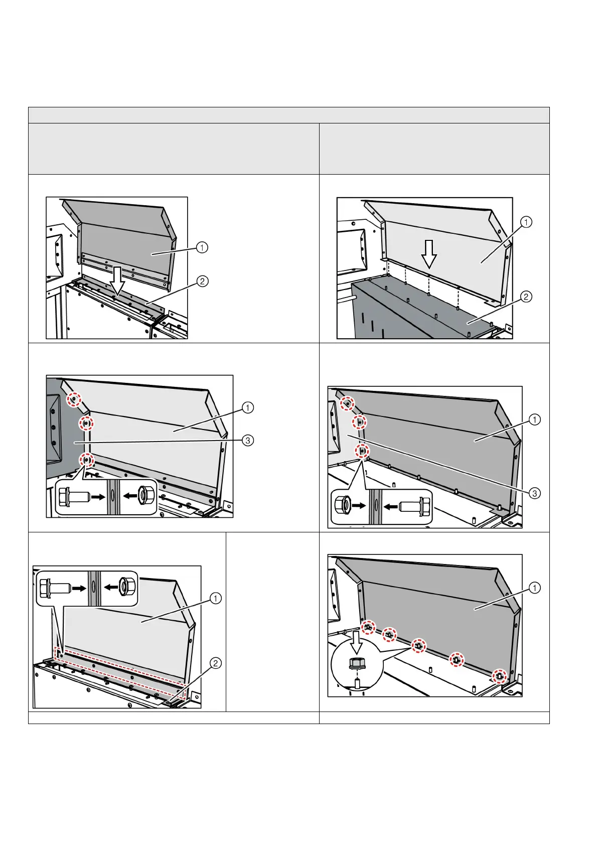
Mounting the rear walls
The installation of the rear evacuation is identical to the installation of a rear wall. The
installation differs depending on the individual panel type and the panel width.
Checking the ventilation flap
For panels
• With a panel width of 600 mm
• With a panel width of 450 mm
• Air-insulated metering panel (aME)
• Auxiliary transformer panel (EB)
Other panel types with a panel width of 900 mm
➭ Push the rear wall ① on the pre-assembled fixing bracket ② . ➭ Place the rear wall ① on the pressure relief duct ② .
➭ Bolt the rear wall ① together with the side plate ③ or another rear wall using
3 bolts M8x20 and nut-and-washer assemblies (tightening torque: 20 Nm).
➭ Bolt the rear wall ① together with the side wall ③ or
another rear wall using 3 bolts M8x20 and nut-and-washer
assemblies (tightening torque: 20 Nm).
➭ Bolt the rear wall ① together with the fixing
bracket ② using bolts M8x20 and nut-and-washer
assemblies (tightening torque: 20 Nm).
Number of bolted joints:
600 mm panel width: 4x
450 mm panel width: 3x
aME: 6x
EB = 6x
➭ Bolt the rear wall together with the rear threaded studs using
5 nut-and-washer assemblies.
➭ Mount further rear walls. ➭ Mount further rear walls.

 Loading...


