Installation
168/293 Revision 11 • INSTALLATION AND OPERATING INSTRUCTIONS • NXPLUS C • 802-9081.9
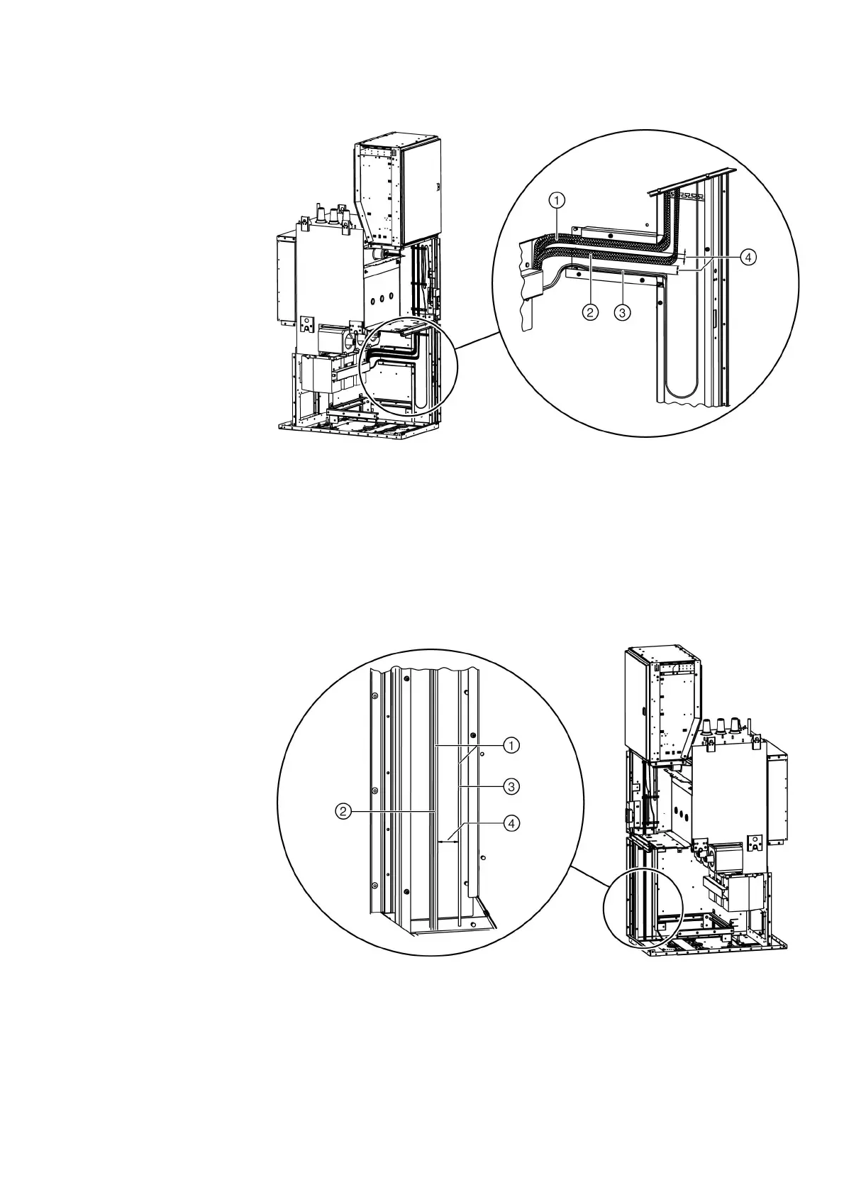
➭ Lay wire groups keeping the maximum possible distance between them, and tight on the
earthed plate.
Laying secondary customer cables in the left-hand wiring duct
For EMC-compatible laying, the cables are divided into functional groups: e.g. group 1 (signal
wires), group 2 (control wires), etc.
➭ Lay wire groups keeping the maximum possible distance between them, and tight on the
earthed plate.
The bus wires and the cables for the circuit-breaker and the three-position switch are
pluggable. The terminals are arranged in the low-voltage compartment.
➭ Lay the cables for the three-position switch and, if required, for the current and voltage
transformers in the low-voltage compartment.
Fig. 130: Wire groups in right-hand wiring duct
①
Current transformer lead
③
Lead of capacitive voltage detecting system
②
Voltage transformer lead
④
Laying wire groups keeping the maximum
possible distance between them
Fig. 131: Wire groups in left-hand wiring duct
①
Customer cable
③
Group2
②
Group1
④
Maximum possible distance between wire groups