802-9081.9 • INSTALLATION AND OPERATING INSTRUCTIONS • NXPLUS C • Revision 11 41/293
Description
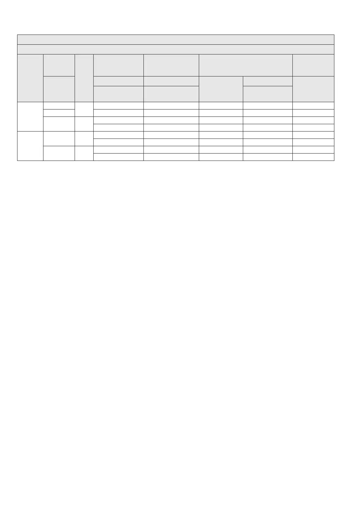
nkt cables 185…500 Silicon
e
1x CB 24-1250-2 3x CC 24-1250-2 - - IEC
95…500 1x CB 24-1250-2* 3x CC 24-1250-2* - - IEC
630…1000 Silicon
e
1x CB 42-1250-3 3x CC 42-2500-3 - - IEC
1x CB 42-1250-3* 3x CC 42-2500-3* - - IEC
Tyco
Electronics
Raychem
25…300 Silicon
e
1x RSTI-58xx 3x RSTI-CC-58xx - - IEC
1x RSTI-58xx* 3x RSTI-CC-58xx* - - IEC
25…300 Silicon
e
1x RSTI-58xx-CEE1 3x RSTI-CC-58xx-CEE1 - - GOST
1x RSTI-58xx-CEE1* 3x RSTI-CC-58xx-CEE1* - - GOST
1
At a continuous current of more than 1150 A, cable sealing ends with tin-plated, nickel-plated or silver-plated cable lugs are required.
2
Observe the actual current- and short-circuit-carrying capacity of the cables and sealing ends.
Circuit-breaker panel 1250 A
1
● Disconnector panel 1250 A
1
Panel spacing 600 mm
Make Conductor
cross-
section
2
Insulation
Cable T-plugs Coupling inserts/
coupling plugs
Surge arresters with coupling inserts According to
standard
[mm
2
] bolted bolted Arresters Coupling inserts
• GOST
(Russia, CIS)
• GB/DL (China)
12 kV
24 kV*
12 kV
24 kV*
additionally