[lo_fault_det_ini_and_reset, 3, en_US]
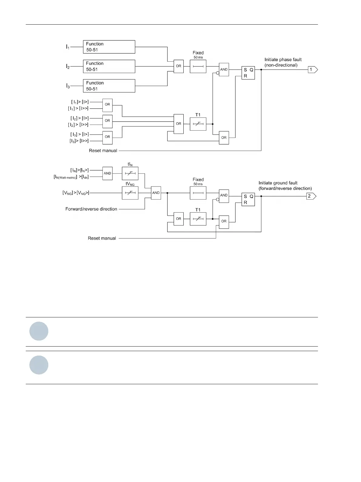
Figure 4-5
Logic Diagram for Fault-Detection Initiation and Fault Reset
For isolated ground:
I
N
(Watt-metric) = I
N
⋅ sin φ
For resonant ground:
I
N
(Watt-metric) = I
N
⋅ cos φ
For more information about ground-fault detection by watt-metric method, refer to chapter 4.1.20 Ground-
Fault Detection with Cos φ/Sin φ Measurement
NOTE
For solid ground or if I
dir
is set to 0, I
dir
is disabled and only I
N
is used for detecting the ground fault.
NOTE
For solid ground or if V
N
> is set to 0, V
NG
is disabled and only I
N
/I
N
(Watt-metric) is used for detecting the
ground fault.
The following logic diagram illustrates the fault indication and fault reset.
Device Functions
4.1 Description
34 SICAM, Feeder Condition Monitor, Manual
E50417-H8940-C580-A4, Edition 03.2019