Installation
Sicore II Installation and Commissioning Guide
667/HB/52600/000 Issue 2 Unrestricted
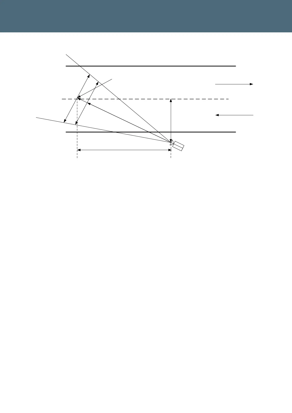
Centre line from capture zone
Traffic direction
Traffic direction
W
DCS
D
Centre of
capture
zone
Camera
position
Skew
distance
S
W1
DCN
Figure 15 – Sicore II Basic Geometry – Top View – With Skew
Both skew and mounting height affect the angle of the camera to the licence plate.
In practice a maximum angle of 46 Degrees should be observed to ensure consistent
camera performance.
Note: This angle is the combination of both lateral and vertical offset of the camera
from the plate. The angle can be seen in the geometry tables in this section.
The camera lens and geometry will usually be determined during survey, generally the
process of selecting the correct camera lens arrangement and geometry is as follows:
• Determine 2 or 3 lane operation
• Identify position of capture zone
• Determine camera pole location and mounting height
• Determine skew value from camera location to centre of capture zone
At this point the tables (Table 15 – Two lane Geometry , Table 16 – Three lane Geometry ,
Table 14 - Geometry Acronyms) can be used to select a suitable lens and Distance D value.
Note that these tables include values for both zero skew and what is considered maximum
skew (beyond which the angle to the licence plate exceeds nominal operating limits).
A geometry spreadsheet ref section 1.3 Is available that automates much of this process and
includes a number of checks to ensure a good geometry selection.
 Loading...