3-11
ET 200L Distributed I/O Device
EWA-4NEB 780600902-05
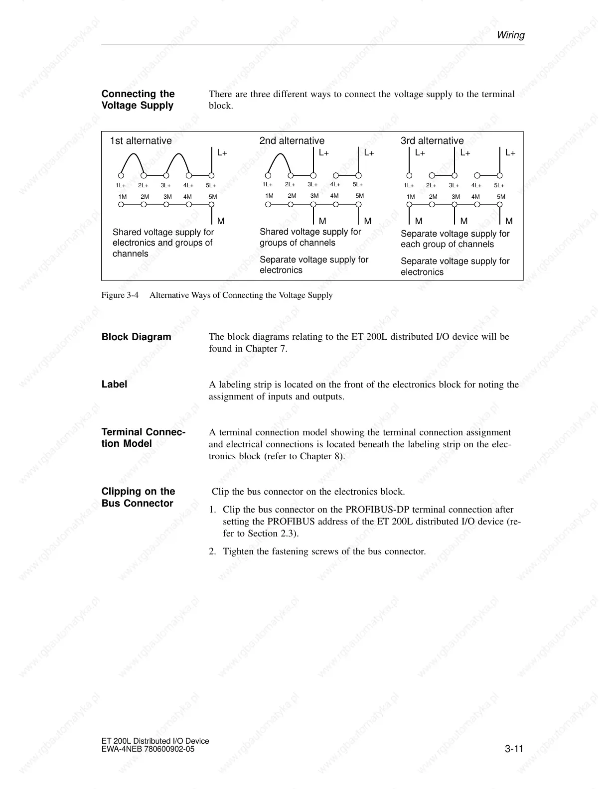
There are three different ways to connect the voltage supply to the terminal
block.
M
L+
1st alternative
Shared voltage supply for
electronics and groups of
channels
M
L+
2nd alternative
Shared voltage supply for
groups of channels
Separate voltage supply for
electronics
L+
M
L+
3rd alternative
Separate voltage supply for
each group of channels
Separate voltage supply for
electronics
L+L+
1L+ 2L+ 3L+ 4L+ 5L+
1M 2M 3M 4M 5M
1L+ 2L+ 3L+ 4L+ 5L+
1M 2M 3M 4M 5M
1L+ 2L+ 3L+ 4L+ 5L+
1M 2M 3M 4M 5M
M MM
Figure 3-4 Alternative Ways of Connecting the Voltage Supply
The block diagrams relating to the ET 200L distributed I/O device will be
found in Chapter 7.
A labeling strip is located on the front of the electronics block for noting the
assignment of inputs and outputs.
A terminal connection model showing the terminal connection assignment
and electrical connections is located beneath the labeling strip on the elec-
tronics block (refer to Chapter 8).
Clip the bus connector on the electronics block.
1. Clip the bus connector on the PROFIBUS-DP terminal connection after
setting the PROFIBUS address of the ET 200L distributed I/O device (re-
fer to Section 2.3).
2. Tighten the fastening screws of the bus connector.
Connecting the
Voltage Supply
Block Diagram
Label
Terminal Connec-
tion Model
Clipping on the
Bus Connector
 Loading...


