8-13
ET 200L Distributed I/O Device
EWA-4NEB 780600902-05
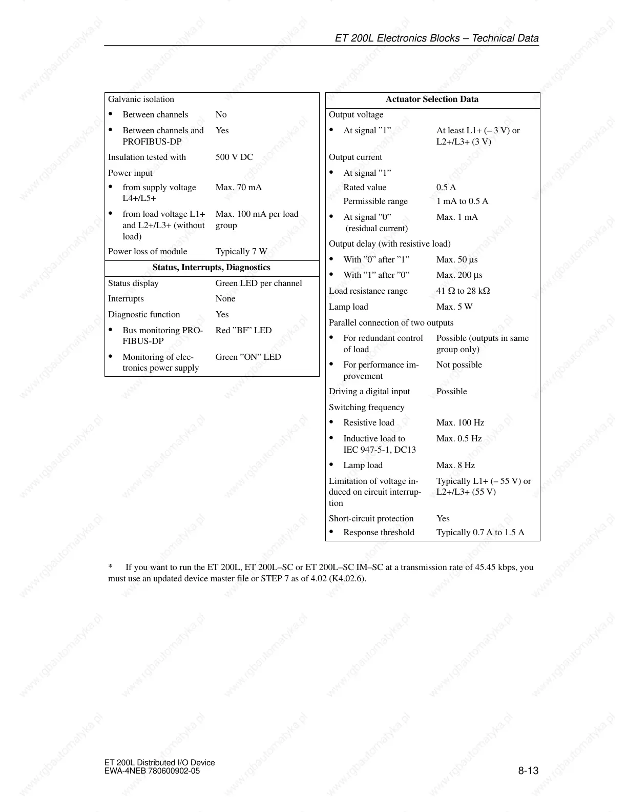
Galvanic isolation
S Between channels No
S Between channels and
PROFIBUS-DP
Yes
Insulation tested with 500 V DC
Power input
S from supply voltage
L4+/L5+
Max. 70 mA
S from load voltage L1+
and L2+/L3+ (without
load)
Max. 100 mA per load
group
Power loss of module Typically 7 W
Status, Interrupts, Diagnostics
Status display Green LED per channel
Interrupts None
Diagnostic function Yes
S Bus monitoring PRO-
FIBUS-DP
Red ”BF” LED
S Monitoring of elec-
tronics power supply
Green ”ON” LED
Actuator Selection Data
Output voltage
S At signal ”1” At least L1+ (– 3 V) or
L2+/L3+ (3 V)
Output current
S At signal ”1”
Rated value
Permissible range
0.5 A
1 mA to 0.5 A
S At signal ”0”
(residual current)
Max. 1 mA
Output delay (with resistive load)
S With ”0” after ”1” Max. 50 µs
S With ”1” after ”0” Max. 200 µs
Load resistance range 41 W to 28 kW
Lamp load Max. 5 W
Parallel connection of two outputs
S For redundant control
of load
Possible (outputs in same
group only)
S For performance im-
provement
Not possible
Driving a digital input Possible
Switching frequency
S Resistive load Max. 100 Hz
S Inductive load to
IEC 947-5-1, DC13
Max. 0.5 Hz
S Lamp load Max. 8 Hz
Limitation of voltage in-
duced on circuit interrup-
tion
Typically L1+ (– 55 V) or
L2+/L3+ (55 V)
Short-circuit protection
S Response threshold
Yes
Typically 0.7 A to 1.5 A
* If you want to run the ET 200L, ET 200L–SC or ET 200L–SC IM–SC at a transmission rate of 45.45 kbps, you
must use an updated device master file or STEP 7 as of 4.02 (K4.02.6).
T 200L Electronics Blocks – Technical Da
 Loading...


