Wiring: Voltage measurement
8
,
6
ದ
0
0
ದ
8
,
6
ದ
0
0
ದ
8
,
6
ದ
0
0
ದ
8
,
6
ದ
0
0
ದ
&+
&+
&+
&+
8
,
6
ದ
0
0
ದ
8
,
6
ದ
0
0
ದ
8
,
6
ದ
0
0
ದ
8
,
6
ದ
0
0
ದ
0
&+
&+
&+
&+
9
9
0
8
/
0
5HI
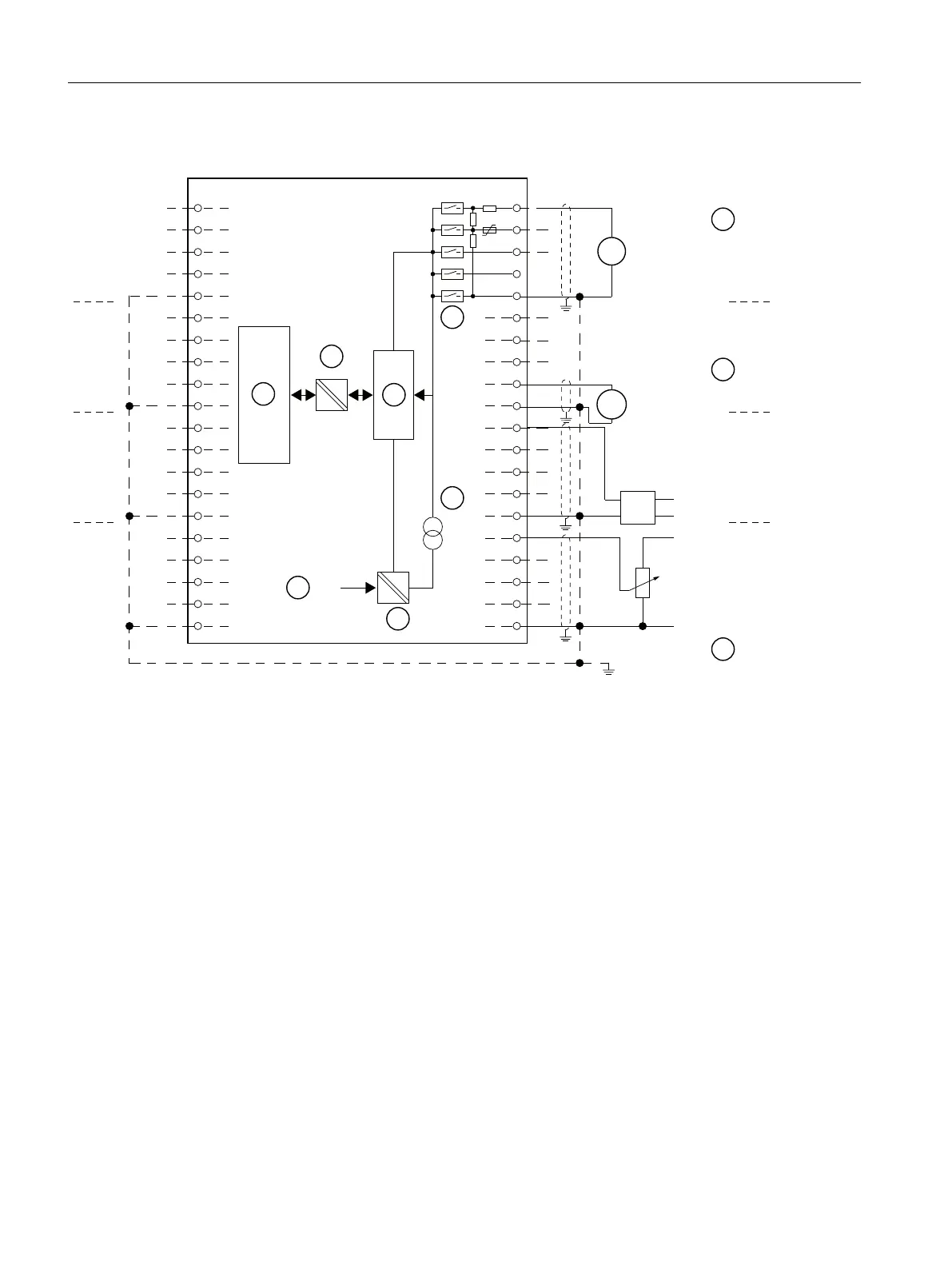
① Voltage measurement: (±5 V, ±10 V, 1 V to 5 V, 0 V to 10 V)
② Voltage measurement (± 50 mV, ± 500 mV, ± 1 V) (note the input resistance defined in the technical data)
③ Equipotential bonding
④ Internal supply
⑤ + 5 V from backplane bus
⑥ Logic and backplane bus interface
⑦ Electrical isolation
⑧ Multiplexer
⑨ Analog to Digital Converter (ADC)
⑩ Current source
Figure 10-6 Block diagram and terminal diagram
ET 200PA SMART I/O modules
10.4 Analog input modules
ET 200PA SMART
154 Operating Instructions, 06/2019, A5E34192013-AB
 Loading...


