The time stamp is only possible for input modules series of modules from the S7-300 series of
modules. Signals of ET 200PA SMART input modules cannot be time-stamped.
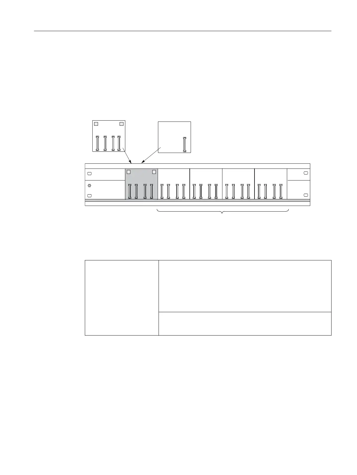
Possible configurations
The length of the mounting rail determines how many active bus modules can be plugged.
%0%0
%0,0,0
%036,0
%0
%0%0
5HGXQGDQF\ZLWK
[,0b
,0b
%0[IRUPPZLGH,2PRGXOHV
Figure 2-4 Configuration with active bus modules
Placement of the PS 307 power supply modules
Redundancy with 2 x IM 650
If you are using the 530 mm mounting rail, place the BM IM/IM in the
rightmost latched position of the two latched positions on the rail Then
you can mount either 2 x PS 307; 2A or 1 x PS 307; 5A on the rail to the
left of the BM IM/IM.
Otherwise you must mount the power supply modules on a separate S7
standard mounting rail.
Recommendation: each IM 650 should have its own PS.
PS 307; 2A fits next to the IM 650 on the BM PS/IM.
PS 307; 5A and 10A do not fit on the BM PS/IM. You must mount these
on a separate S7 standard mounting rail.
Assignment planning
2.2 Configuring the mechanical structure
ET 200PA SMART
Operating Instructions, 06/2019, A5E34192013-AB 21
 Loading...


