Diagnostic messages and possible corrective measures
The table below provides an overview of the diagnostic messages of the AI 8 x 16 Bit.
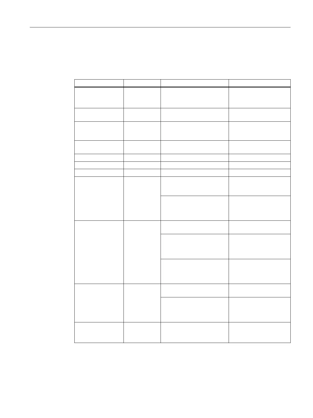
Table 10-12 Diagnostic messages of the AI 8 x 16 Bit and possible corrective measures
Diagnostic message Configurable Possible cause of error Corrective measure
External auxiliary volt‐
age
missing
No No supply voltage L+ of the
module
Feed supply L+
Module parameters
not assigned
No Startup error Reassign the module pa‐
rameters
Incorrect parameters No One parameter, or the combi‐
nation of parameters, is not
plausible
Reassign the module pa‐
rameters
Time monitoring trip‐
ped
No Intermittently high electromag‐
netic interference
Eliminate the interference
EPROM error No Module defective Replace the module
RAM error No Module defective Replace the module
ADC/DAC error No Module defective Replace the module
Parameter assign‐
ment error
No One parameter, or the combi‐
nation of parameters, is not
plausible
Reassign the module pa‐
rameters
The wire jumper (terminals 10
and 11) does not match the pa‐
rameter assignment of the
measurement type.
Check wire jumper
Wire break Yes The connection of the trans‐
ducer is interrupted
Check the wiring
Resistance of sensor protec‐
tion circuit too high
Use a different type of sen‐
sor or modify the wiring, for
example, use cables with
larger cross-section
Channel not connected (open) Disable the channel group
("Measurement type" pa‐
rameter) or connect the
channel
Low limit violation of
measuring range / un‐
derrange
Yes
(Group diag‐
nostics)
Analog value below the under‐
range
Check the measuring range
selection
In the case of measuring range
4 mA to 20 mA, sensor may be
connected with reverse polari‐
ty.
Check terminals
High limit violation of
measuring range / un‐
derrange
Yes
(Group diag‐
nostics)
Analog value above the over‐
range
Assign a different measur‐
ing range
ET 200PA SMART I/O modules
10.4 Analog input modules
ET 200PA SMART
Operating Instructions, 06/2019, A5E34192013-AB 175
 Loading...


