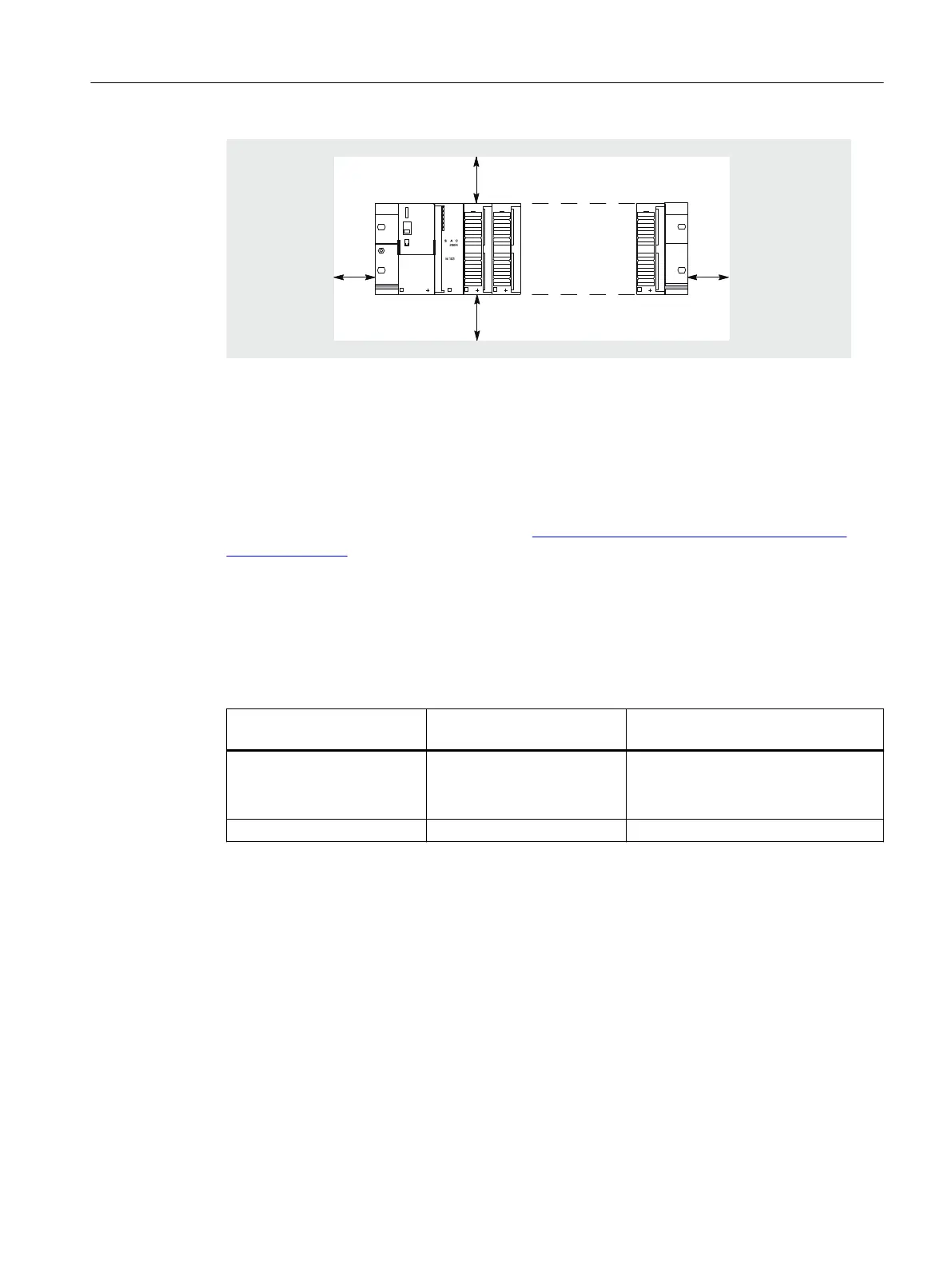
Figure 2-2 Clearances for an ET 200PA SMART configuration on a rack
Mounting dimensions of the modules
You can find the mounting dimensions of the ET 200PA SMART module in section Dimensional
drawings of the signal modules (Page 211) of this manual.
You can find the mounting dimensions of the modules of the S7-300 range in the "S7-300
automation system, module specifications (
http://support.automation.siemens.com/WW/
view/en/8859629)" reference manual.
The mounting dimensions of the IM 650 interface modules can be found in section "Technical
specifications of the IM 650 (Page 118)".
Lengths of the mounting rails
Depending on your configuration, you can use the following mounting rails:
Mounting rail for mounting of
active bus modules
Usable length for modules Remark
482.6 mm
530 mm
620 mm
450 mm
480 mm
580 mm
Comes with fixing holes.
2000 mm Cut to length required Fixing holes have to be drilled.
See also
Connecting shielded cables via a shield connecting element (Page 49)
Installing the DIN rail (Page 32)
Assignment planning
2.2 Configuring the mechanical structure
ET 200PA SMART
Operating Instructions, 06/2019, A5E34192013-AB 19
 Loading...


