Components and protective measures
A variety of components and protective measures are prescribed for setting up a complete
plant. The nature of the components and the extent to which the protective measures are
binding depends on which DIN VDE directive applies to your plant configuration. The following
table refers to the two following figures.
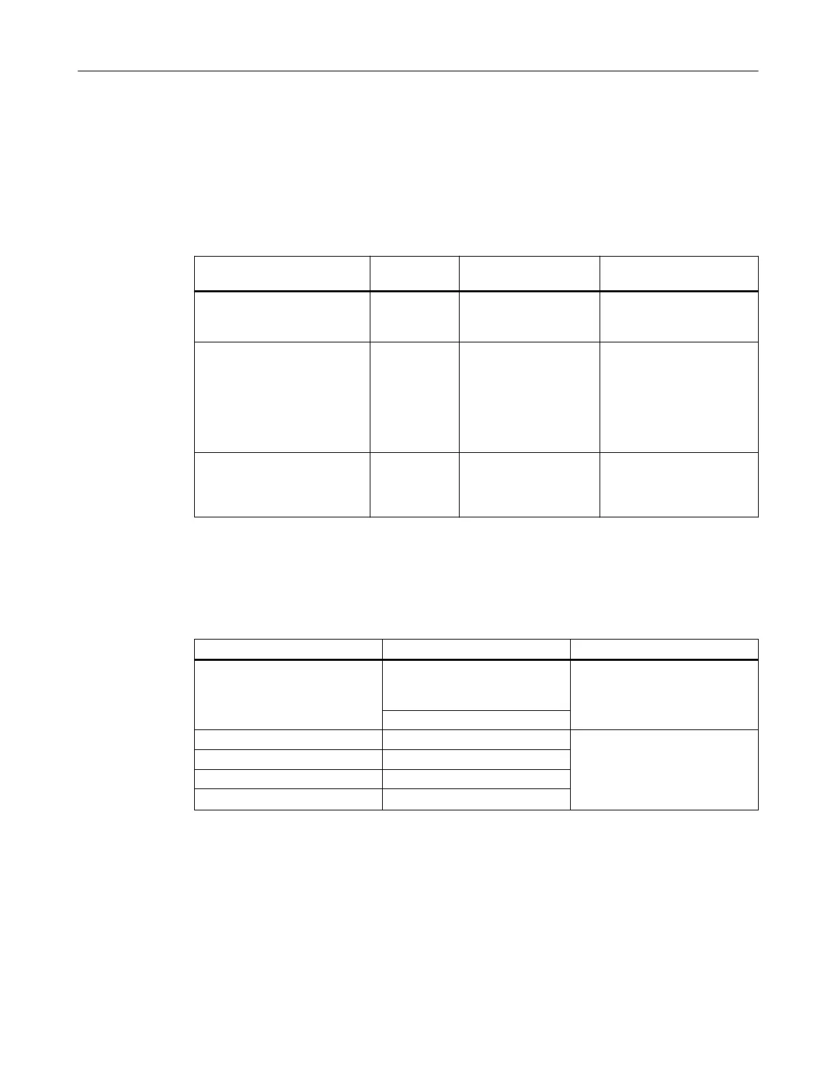
Table 2-1 DIN VDE directives for the configuration of a controller
Comparisons ... Reference to
figure
DIN VDE 0100 DIN VDE 0113
Disconnecting devices for con‐
troller, transducers and final
controlling elements
(1) … part 460:
Main switch
… part 1:
Disconnector
Short-circuit and overload pro‐
tection:
in groups for transducers and
final controlling elements
(2) … part 725:
Single-pole fusing of cir‐
cuits
… part 1:
● For grounded
secondary circuit:
single-pole fusing
● otherwise: all-pole
fusing
Load power supply for AC load
circuits with more than five
electromagnetic equipment
items
(3) Galvanic isolation with
transformers recom‐
mended
Galvanic isolation with
transformers required
Properties of load power supplies
The load power supply supplies input and output circuits (load circuits) as well as sensors and
actuators. The properties of load power supplies that are required in specific application cases
are listed below.
Properties of load power supply required for ... Remarks
Safer (electrical) isolation Modules that must be supplied
with voltages ≤ 60 V DC or
≤ 25 V AC
The PS 307 power supplies as
well as the Siemens load power
supplies of the 6EP1 series have
this property.
24 V DC load circuits
Tolerances of the output voltage: In the case of significant ripple of
the output voltage, we recom‐
mend using a supporting capaci‐
tor. Rating: 200 µF per 1 A load
current (with bridge rectification).
20.4 V to 28.8 V 24 V DC load circuits
40.8 V to 57.6 V 48 V DC load circuits
51 V to 72 V 60 V DC load circuits
Rule: ground the load circuits
The load circuits should be grounded.
The common reference potential (ground) ensures correct operational reliability. Provide a
disconnectable connection to the protective conductor at the external power supply (terminal L-
or M) or the isolation transformer (position ④ in the following figure). In the event of power
distribution problems, this measure makes it easier for you to localize ground faults.
Assignment planning
2.3 Configuring the electrical structure
ET 200PA SMART
Operating Instructions, 06/2019, A5E34192013-AB 25
 Loading...


