The parameter assignment is made via HW Config as “4WMT current”
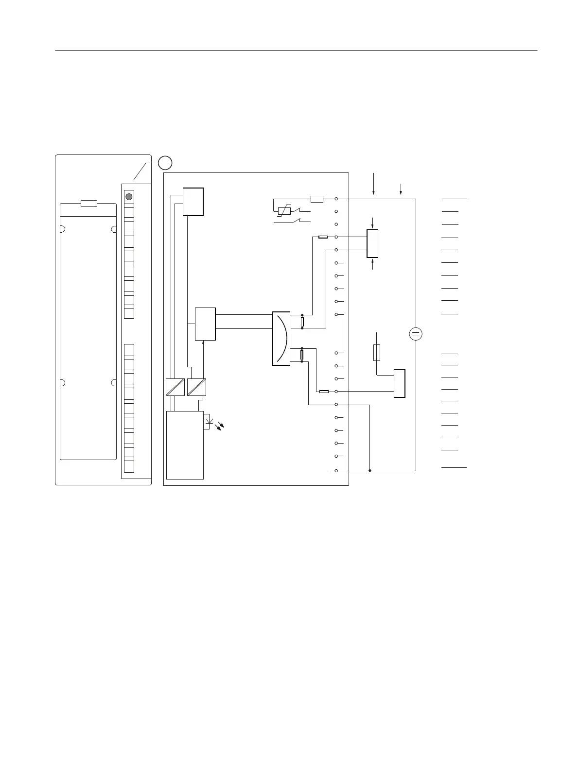
The 4-wire transducers have a separate supply voltage.
You can also use a 2-wire transducer with separate fused supply. This is shown in the figure
below using channel 5 as an example.
1
6)
0
/
6)
˩3
$'8
:LUH
:LUH
9
[
0
&+
0
/
0
0
&+
0
&+
0
0
0
&+
0
0
0
0
&+
0
0
&+
0
0
&+
0
0
&+
0
0
8Y
8Y
/
(OHFWULFDO
LVRODWLRQ
/RJLFDQG
EDFN
SODQHEXV
LQWHUIDFH
ZLUHWUDQVGXFHU
6KRUWFLUFXLWSURWHFWLRQ
7UDQVGXFHUV
ZLUHWUDQVGXFHU
+DUGZDUHVHWWLQJIRURSHUDWLRQZLWK
ZLUHWUDQVGXFHU
0HDVXULQJ
PXOWLSOH[HU
① Group error display - red (SF LED)
Figure 10-10 Module view and block diagram of the AI 8 x 16 Bit in 4-wire transducer mode
ET 200PA SMART I/O modules
10.4 Analog input modules
ET 200PA SMART
Operating Instructions, 06/2019, A5E34192013-AB 167
 Loading...


