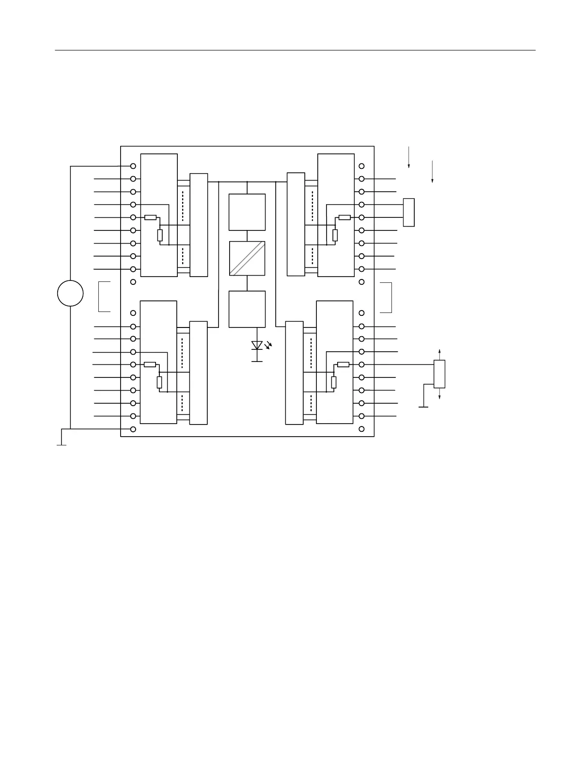
You can also use a 4-wire transducer with separate supply. This is shown in the figure below
using channel 13 as an example.
:LUH
:LUH
8Y
8Y
ADC
M
2
3
4
5
6
7
8
9
12
13
14
15
16
17
18
19
20
1
10
11
22
23
24
25
26
27
28
29
32
33
34
35
36
37
38
39
40
21
30
31
M0+
M0-
M1+
M1-
M2+
M2-
M3+
M3-
M4+
M4-
M5+
M5-
M6+
M6-
M7+
M7-
M8+
M8-
M9+
M9-
M10+
M10-
M11+
M11-
M12+
M12-
M13+
M13-
M14+
M14-
M15+
M15-
M
L+
SF
200 Ω
50 Ω
M
200 Ω
50 Ω
M
200 Ω
50 Ω
M
200 Ω
50 Ω
M
M
DC
24V
ZLUHWUDQVGXFHU
ZLUHWUDQVGXFHU
Electrical
isolaon
BUS
ASIC
+DUGZDUHVHWWLQJIRURSHUDWLRQZLWK
ZLUHWUDQVGXFHU
5HGXQGDQF\MXPSHU
Mulplexer
Mulplexer
Mulplexer
Mulplexer
Figure 10-11 AI 16 x 16 Bit with 2-wire transducer operation
Wiring and block diagrams of the AI 16 x 16 Bit with 4-wire transducer operation
When the module is used for 4-wire transducer operation, terminals 10 and 11 must not be
jumpered.
All channels of the module operate in 4-wire transducer mode in this case. Shown using
channel 9 as an example.
The parameter assignment is made via HW Config as “4WMT current”
The 4-wire transducers have a separate supply voltage.
You can also use a 2-wire transducer with separate fused supply. This is shown in the figure
below using channel 13 as an example.
ET 200PA SMART I/O modules
10.4 Analog input modules
ET 200PA SMART
Operating Instructions, 06/2019, A5E34192013-AB 177
 Loading...


