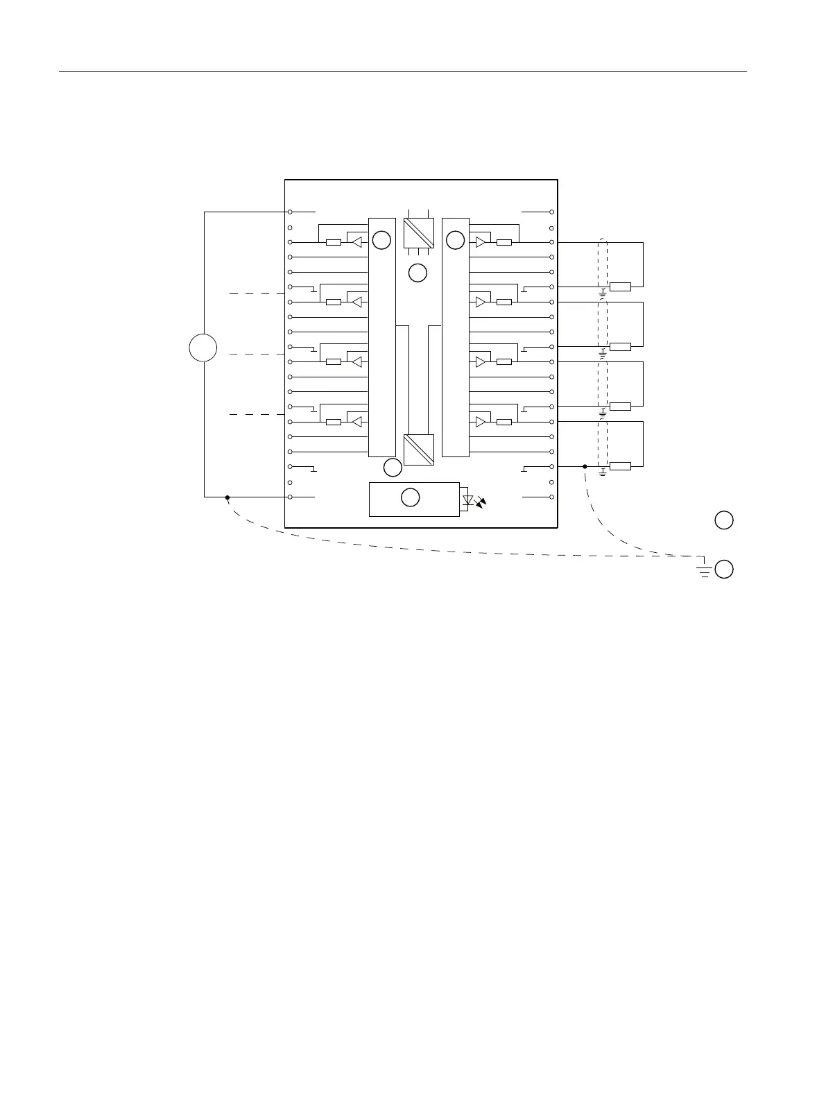
Connection and current output block diagram
The wiring examples apply to all channels (channels 0 to 7).
9
0
9
'&
/0
0
&+
&+
&+
&+
6)
&+
&+
&+
&+
4,
0
$1$
4,
0
$1$
4,
0
$1$
4,
0
$1$
① DAC
② Internal supply
③ Equipotential bonding
④ Functional ground
⑤ Backplane bus interface
⑥ Electrical isolation
Figure 10-15 Wiring and block diagram
Non-connected channels
So that non-connected output channels of the AO 8 x 12 Bit are de-energized, you must set the
"Output type" parameter as "disabled". Disabled channels can remain unconnected.
Connection of loads and actuators
You must connect loads to CHx + and the reference point of the analog circuit CHx – of a current
output.
Redundant use
In redundant mode, the AO8x12Bit modules are present in duplicate and are configured and
operated redundantly.
ET 200PA SMART I/O modules
10.5 Analog output modules
ET 200PA SMART
204 Operating Instructions, 06/2019, A5E34192013-AB
 Loading...


