Connecting
3.1 Wiring and block diagram
ET 200SP F-TM Count 1x1Vpp sin/cos HF (6ES7136-6CB00-0CA0)
Equipment Manual, V1.0, 01/2021, A5E47073911-AA
25
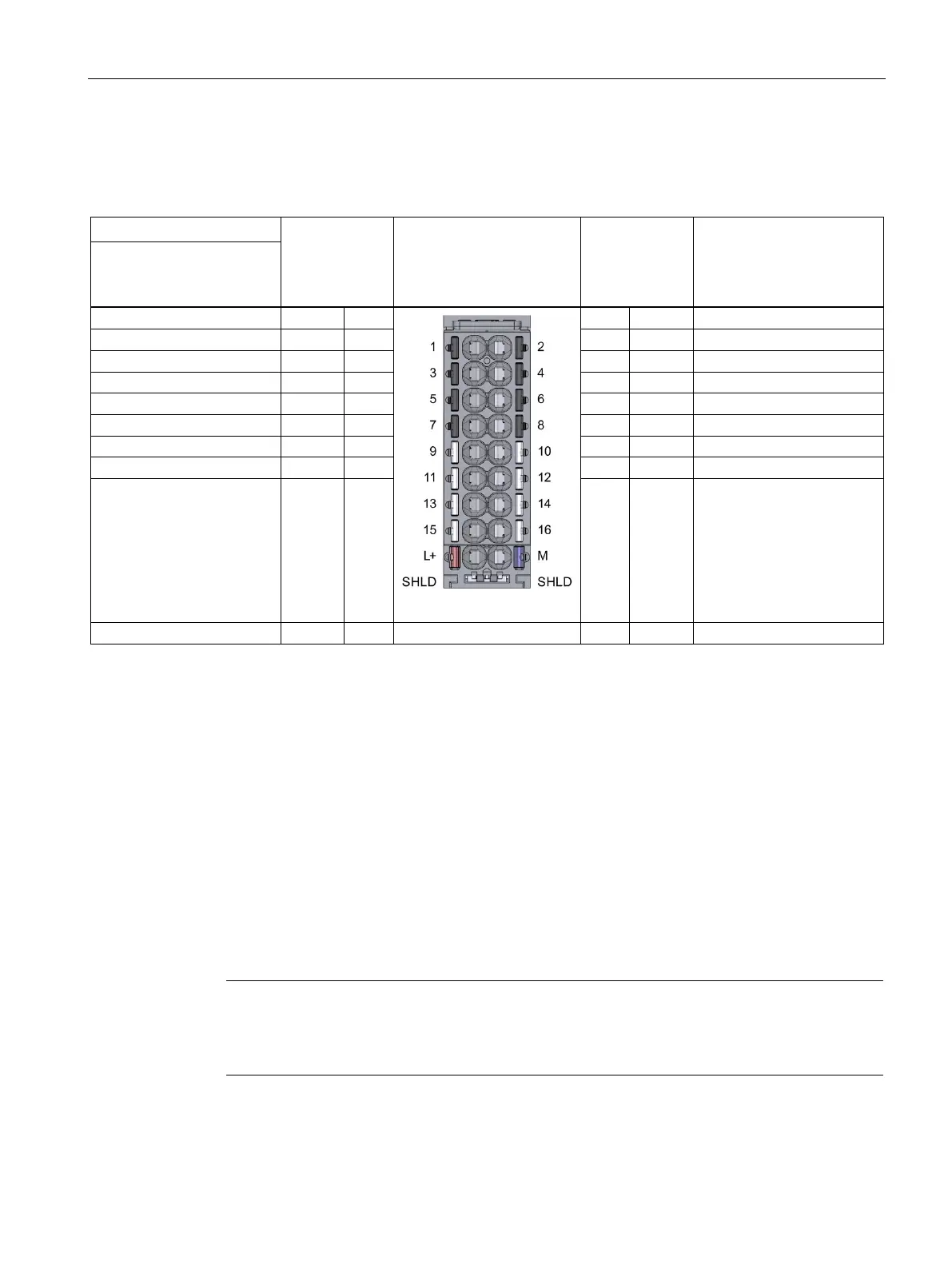
Pin assignment of the BaseUnit
Table 3- 1 Pin assignment of BaseUnit BU15-P16+A10+2B, BU type A0
Signal name View Signal
name
Designation
SIN/COS differential
encoder with or without
Ground for supply voltage
Supply voltage L+/M
You connect the supply voltage to terminals L+ and M on a light BaseUnit. For a dark
BaseUnit, the supply voltage of the module to the left is used. An internal protection circuit
protects the F-TM Count module from reverse polarity of the supply voltage. The F-TM Count
module monitors whether the supply voltage is connected.
Encoder supply
The encoder supply from the F-TM Count module provides 5 V DC encoder sensor supply
voltage. The encoder supply is only switched off during the following occurrences:
• There is a fatal error
• There is a firmware update in progress
-TM Count module can only support 5 V DC encoders using the module's inte
rnal sensor
supply. However, 10 to 30 V DC incremental encoders can be supported when externally
powered.

 Loading...


